2 master mode operation, 3 master clock, 1 master mode speed selection – Cirrus Logic CS5344 User Manual
Page 13: Master mode speed
DS687F4
13
CS5343/4
Draft
2/1/11
4.1.2
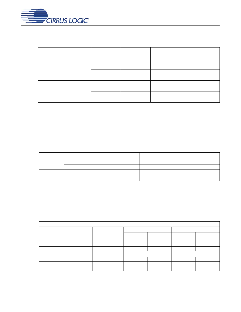
Master Mode Operation
As clock Master, the CS5343/4 generates LRCK and SCLK synchronously on-chip.
shows the
available sample rates and associated clock ratios in Master Mode.
4.1.2.1
Master Mode Speed Selection
During power-up in Master Mode, the LRCK and SCLK pins are inputs to configure speed mode and the
output clock ratio. The LRCK pin is pulled low internally to select Single-Speed Mode by default, but Dou-
ble-Speed Mode is accessed with a 10 k
pull-up resistor from LRCK to VA as shown in
. Simi-
larly, the SCLK pin is internally pulled-low by default to select a 256x/512x MCLK/LRCK ratio, but a
MCLK/LRCK ratio of 348x/768x is accessed with a 10 k
pull-up resistor from SCLK to VA as shown in
. Following the power-up routine, the LRCK and SCLK pins become clock outputs.
4.1.3
Master Clock
The CS5343/4 requires a Master clock (MCLK) which runs the internal sampling circuits and digital filters.
There is an internal automatic MCLK divider which is activated based on the input frequency of MCLK.
This divider selection allows the high and low MCLK speeds in a given speed mode (i.e. 256x and 512x
in SSM).
lists some common audio output sample rates and the required MCLK frequency.
Speed Mode
MCLK/LRCK
Ratio
SCLK/LRCK
Ratio
Input Sample Rate Range (kHz)
Single-Speed Mode
256x
64
43 - 54
512x
64
43 - 54
384x
64
43 - 54
768x
64
43 - 54
Double-Speed Mode
128x
64
86 - 108
256x
64
86 - 108
192x
64
86 - 108
384x
64
86 - 108
Table 3. Speed Modes and the Associated Sample Rates (Fs) in Master Mode
Pin
Resistor Option
Clock Configuration
LRCK
Internal Pull-Down to GND (100 k
)
Single-Speed Mode (default)
External Pull-Up to VA (10 k
)
Double-Speed Mode
SCLK
Internal Pull-Down to GND (100 k
)
128x/256x/512x MCLK/LRCK (default)
External Pull-Up to VA (10 k
)
192x/384x/768x MCLK/LRCK
Table 4. Speed Mode Selection in Master Mode
Master and Slave Mode
Sample Rate (kHz)
Speed Mode
MCLK(MHz)
MCLK (MHz)
256x
512x
384x
768x
32 (*Slave Mode Only)
SSM
*8.192
*16.384
*12.288
*24.576
44.1
SSM
11.289
22.579
16.934
33.868
48
SSM
12.288
24.576
18.432
36.864
Sample Rate (kHz)
Speed Mode
MCLK(MHz)
MCLK (MHz)
128x
256x
192x
384x
88.2
DSM
11.289
22.579
16.934
33.868
96
DSM
12.288
24.576
18.432
36.864
Table 5. Common MCLK Frequencies in Master and Slave Modes