3 firmware messaging, 1 communication overview, 1 writing to the dsp – Cirrus Logic AN333 User Manual
Page 8: 2 solicited read
8
AN333
3 Firmware Messaging
3 Firmware Messaging
While using the CS470xx, it is necessary to communicate with the DSP in order to control or monitor the various
downloaded firmware modules. We refer to this process of communication as firmware messaging. The purpose of this
section is to describe the types and formats of these firmware messages. In general, the user can control the firmware
module running on the DSP with firmware messaging, and subsequently perform various tasks including the following:
•
Configure the module after firmware download (such as kick-starting the DSP)
•
Change runtime parameters (such as adjusting the volume or switching Pro Logic II modes)
•
Obtain information from the DSP (such as the current state of the firmware registers or data stream information)
3.1 Communication
Overview
From a microprogramming point of view, the CS470xx firmware modules can be thought of as blocks of several 32-bit
registers (variables) that either control the behavior of the firmware or store information about the state of the firmware at
the time of operation. Each register has a unique index. Access to the register involves a combination of a specified opcode
for that firmware module together with the register index. For each firmware module, the following opcodes are available:
•
Write Opcode—Issues a command to write to a specific module.
•
Read Opcode—Issues a command to read from a specific module.
•
Read-response Opcode—Indicates the module and index that have been read.
These available opcodes permit the following types of communication with the CS470xx DSP:
•
Writing to the DSP
•
Solicited read from the DSP
•
Unsolicited read from the DSP
3.1.1
Writing to the DSP
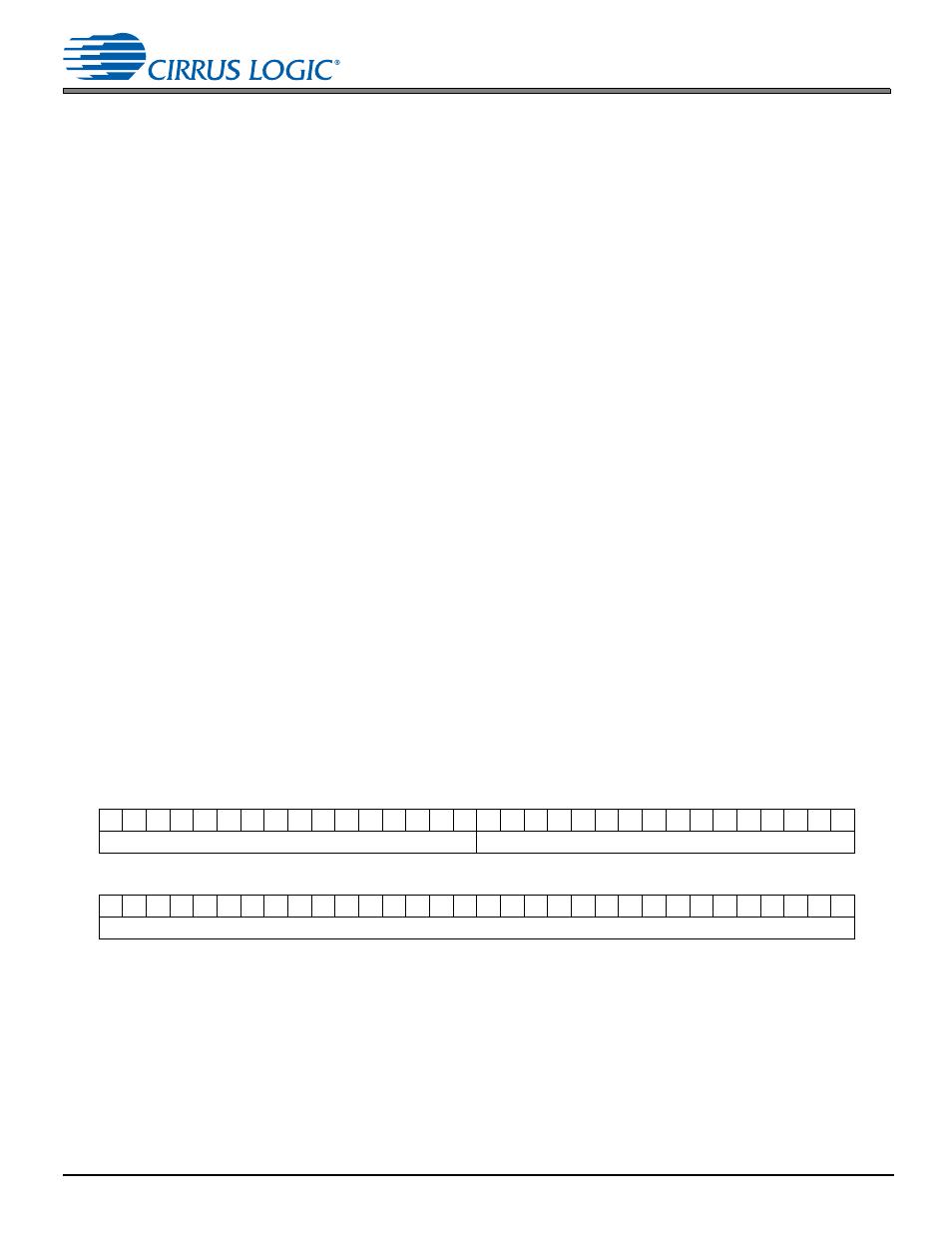
A write session with the CS470xx consists of one 8-byte message from the host to the CS470xx. The write message
consists of a 32-bit command word followed by a 32-bit data word (that is, data to be written to the register). The command
word is formed by combining the write opcode for that module with the index of the register that needs to be written. The
32-bit data word is the value of the data intended to fill that register.
shows the format of a write message:
Figure 3-1. Write Command and Write Data Words
3.1.2
Solicited Read
A solicited read can be thought of as a request to read the contents of a specific register. A solicited read is composed of
a 32-bit solicited read-command word, which is a request to read a specific index (register) in a given module or read up
to sixteen consecutive indices. The DSP, upon receiving this message, responds by sending back a 32-bit read-response
opcode and the requested 32-bit data word(s) contained in each of the indices read.
Write Command Word:
31 30 29 28 27 26 25 24 23 22 21 20 19 18 17 16 15 14 13 12 11 10 9
8
7
6
5
4
3
2
1
0
OPCODE[31:16]
INDEX[15:0]
Write Data Word:
31 30 29 28 27 26 25 24 23 22 21 20 19 18 17 16 15 14 13 12 11 10 9
8
7
6
5
4
3
2
1
0
DATA WORD[31:0]