2 pcm manager in dsp composer – Cirrus Logic AN333 User Manual
Page 26
26
AN333
6.2 PCM Manager in DSP Composer
6.2 PCM Manager in DSP Composer
All configuration information described in
can be controlled in DSP Composer. I/O buffer channel availability
is device specific. The PCM Manager is part of the System block. To insert a System block, drag it onto the workspace.
When the System block is on the workspace, the runtime and pre-kick controls for the PCM Manager can be accessed by
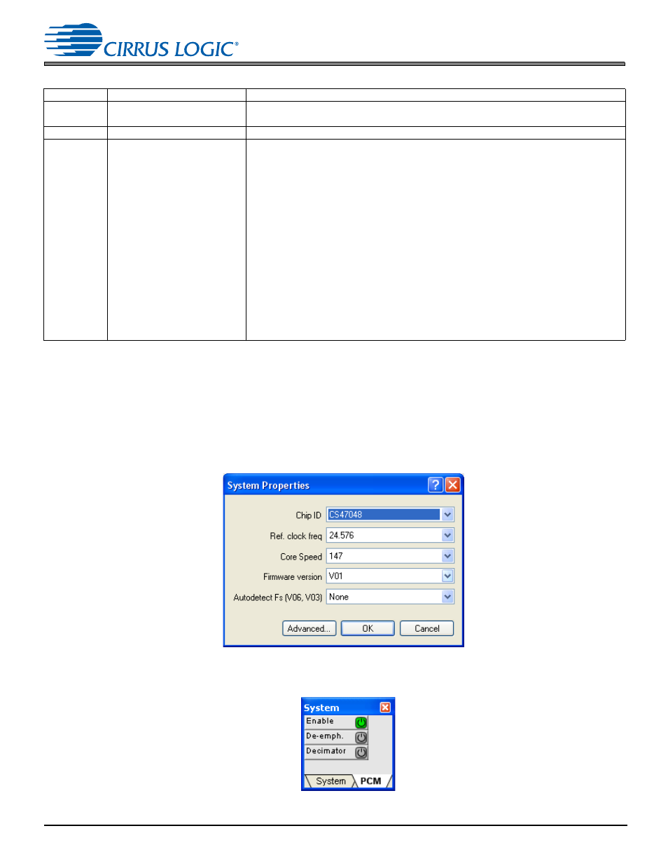
double-clicking the System block. When the System Block is first dragged onto the workspace, the user is prompted to
select device and input mode as seen in
. These settings can also be accessed by right-clicking the System block
and selecting Device Properties.
Figure 6-1. DSP Composer System Block Device Properties
The runtime controls are accessed by double-clicking the System Block as shown in
.
Figure 6-2. DSP Composer PCM Manager Runtime Controls
0x000C
IO_BUFF_CH11_SOURCE
Input source for Aux Channel 11 I/O buffer
Default = 0x00000000
0x000D
Reserved
Reserved
0x000E
PCM_INPUT_MODE
Bit 31: 0/1 Disable/enable LFE processing through PCM input
Bits 3:0 Input Mode
(number of input channels present in the system)
0x0 = 2/0 Lt, Rt Dolby Surround compatible
0x1 = 1/0 C
0x2 = 2/0 L/R
0x3 = 3/0 L/C/R
0x4 = 2/1 L/R/S
0x5 = 3/1 L/C/R/S
0x6 = 2/2 L/R/Ls/Rs
0x7 = 3/2 L/C/R/Ls/Rs
0x8 = 3/3 L/C/R/Ls/Rs/Cs
0x9 = 3/4 L/C/R/Ls/Rs/Sbl/Sbr
0xA = 2/3 L/R/Ls/Rs/Cs
0xB = 2/4 L/R/Ls/Rs/Sbl/Sbr
Default = 0x00000002
Table 6-1. PCM Manager (Cont.)
Index
Variable
Description