2 spdif in to stereo speaker out, Figure 2. spdif in to stereo speaker out, Figure 2.spdif in to stereo speaker out – Cirrus Logic CDB43L22 User Manual
Page 9: Cdb43l22, S/pdif in
DS792DB1
9
CDB43L22
3.2
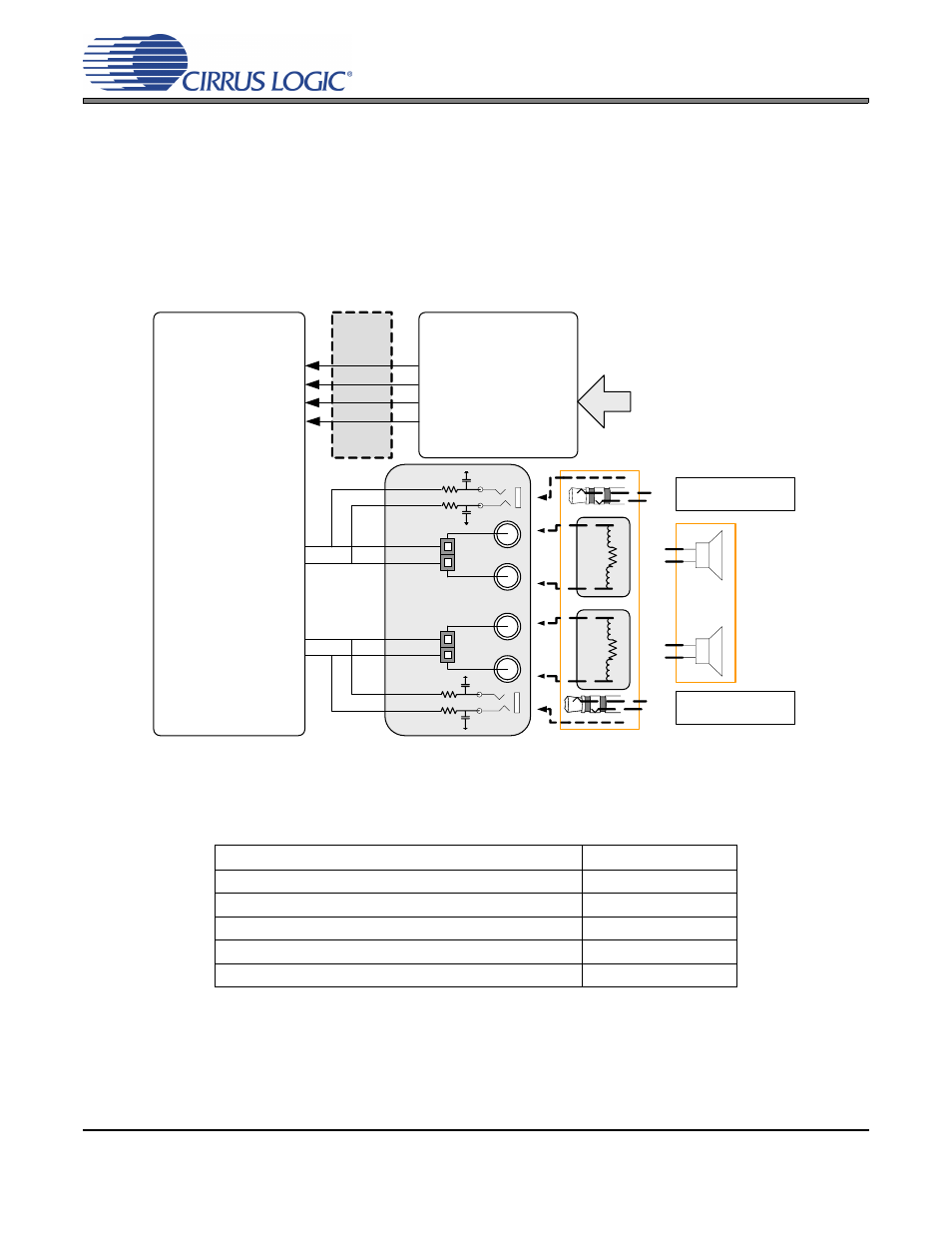
SPDIF In to Stereo Speaker Out
The CS43L22’s stereo differential PWM speaker output performance can be tested by loading the “SPDIF
In to Stereo Speaker Out” quick setup file provided with the software package. The script configures the
digital clock and data signal routing on the board as shown in
.
Stereo output jacks J6 and J18 can be used to monitor filtered PWM output for measurement purposes. The
figure shows how a real speaker or a speaker model should attach to the binding posts during performace
tests. Digital S/PDIF input can be provided on the optical (OPT2) or RCA (J68) jacks. Refer to
for details on software configuration.
Figure 2.
SPDIF In to Stereo Speaker Out
shows the expected performance characteristics one should expect when using the CDB43L22 for
SPDIF In to Stereo Speaker Out measurements.
Table 2.
SPDIF In to Stereo Speaker Out
Performance Plots
Plot
Location
FFT - S/PDIF In to Speaker Out @ 0 dBFS
FFT - S/PDIF In to Speaker Out @ -60 dBFS
Frequency Response- S/PDIF In to Speaker Out
THD+N - S/PDIF In to Speaker Out
THD+N vs. Output Power- S/PDIF In to Speaker Out
Real
Speaker
Load
FPGA
CS43L22
CS8416
S/PDIF Rx
RX.RMCK
RX.LRCK
RX.SCLK
RX.SDOUT
S/PDIF
IN
Pin 4 – SPKOUTA+
Pin 6 – SPKOUTA-
Pin 7 – SPKOUTB+
Pin 9 – SPKOUTB-
8
Ω
Spkr A
Spkr B
J6
J18
(MASTER)
(SLAVE)
15 µH
15 µH
J15
J19
30 kHz filter for
measurement
30 kHz filter for
measurement
8
Ω
15 µH
15 µH
Test Load
+
-
+
-
MCLK
LRCK
SCLK
SDIN
Measurement for
Ch. A
Measurement for
Ch. B
OR