Quick start guide – Cirrus Logic CDB43L22 User Manual
Page 7
DS792DB1
7
CDB43L22
2. QUICK START GUIDE
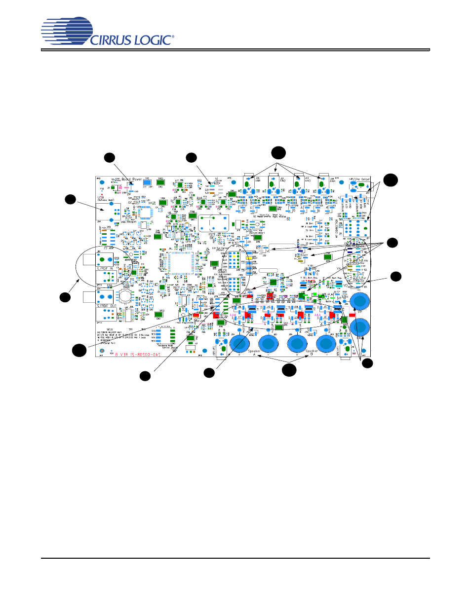
The following figure is a simplified quick start up guide made for user convenience. The following start up guide con-
figures the board with a 1.8 V power supply to VL, VA, VA_HP and VD. The user may choose from steps 9 through
13 depending on the desired measurement. Refer to
for details on how the various components
on the board interface with each other in different board configuration modes. Refer to
for
descriptions on control settings in the Cirrus FlexGUI software.
Provide analog line level inputs via AIN1,
AIN2, AIN3, AIN4 for testing the part in
passthrough mode.
Set VL to 1.8 V by
shunting top 2 pins.
Shunt bottom 2 pins to
receive board power from
USB +5 V DC power.
Connect USB to board.
Open Flex GUI software
on PC and load quick
setup script.
*See section 3 for quick
setup descriptions.
Provide S/PDIF
input to board via
J61 or OPT3.
PCM digital audio input can
also be provided to the
board via header J78.
Shunt the left 2 pins on all rows
of headers J8 and J109.
Connect a ribbon cable to right 2
pins of all rows if external system
connect is required.
Shunt left 2 pins of
jumpers J16, J13,
J20, J11, J17, J14,
J23 and J12.
Receive differential left and right channel
PWM speaker output via binding posts or
30 kHz filtered signal for measurements
via stereo jacks J18 and J6.
*Refer to section 3 for quick setup
descriptions.
Connect power source of 4.5 V between
VP and GND or connect 3 1.5 V AAA
batteries on back of board with correct
polarities. Specify the power source by
shunting appropriate pins on J5.
Select the value of
VA, VA_HP and VD
as 1.8 V by shunting
the top 2 pins of J25,
J36 and J28
respectively.
Shunt left two pins on
J1 and J2.
Monitor Headphone/
Line Output via stereo
jacks J40, J21.
*Refer to section 3
and 4 for software
and hardware
configuration settings.
Shunt J74, J47,
J53, J52 and J48.
1
2
3
4
5
6
7
8
9
10
11
12
13
CDB43L22
CS43L22