Jumper settings, Table 5. jumper settings, Table 5 on – Cirrus Logic CDB43L22 User Manual
Page 18
18
DS792DB1
CDB43L22
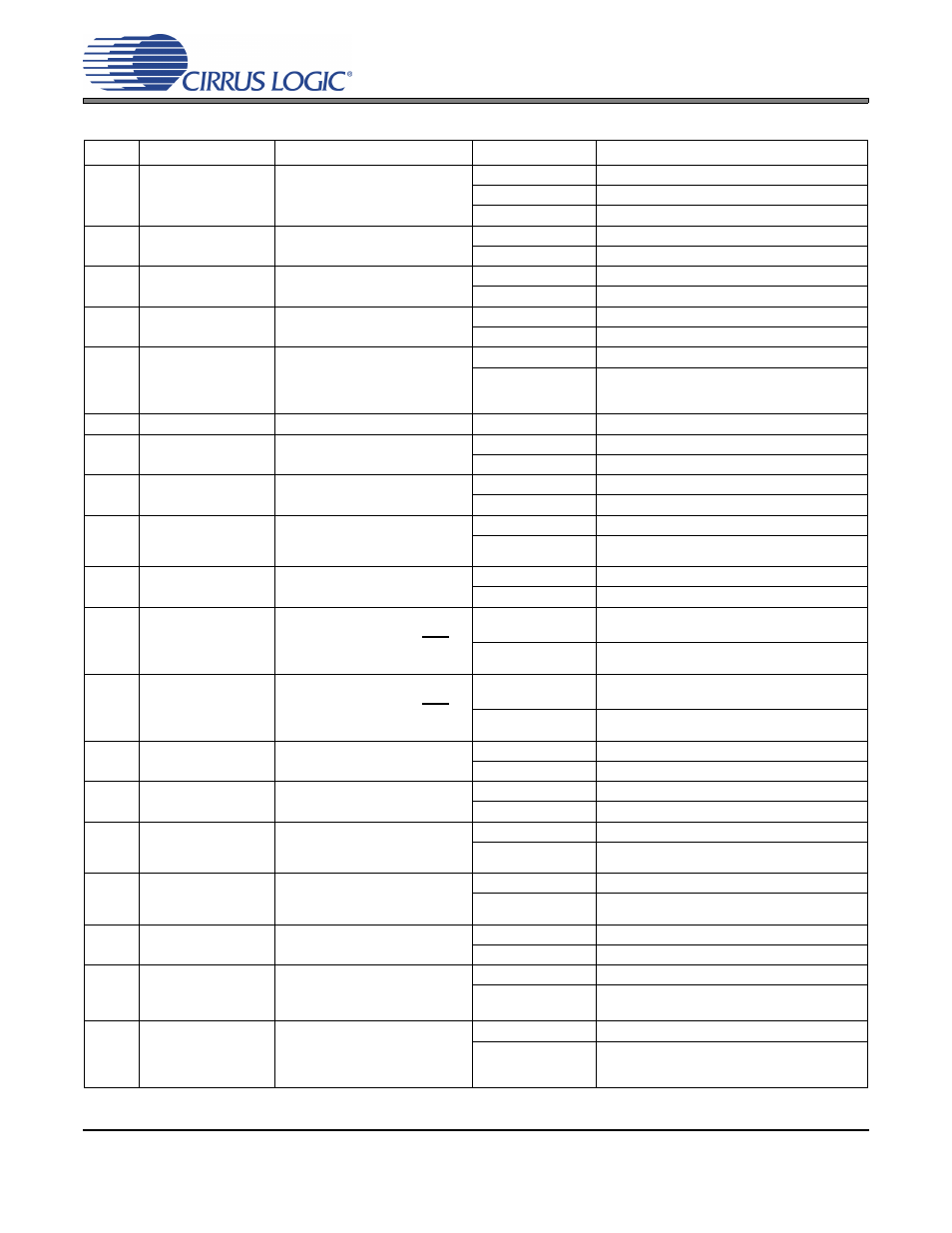
6. JUMPER SETTINGS
JMP
LABEL
PURPOSE
POSITION
FUNCTION SELECTED
J31
VL
Selects source of voltage for the
VL supply
*+1.8V
Voltage source is +1.8 V regulator.
+2.5V
Voltage source is +2.5 V regulator.
+3.3V
Voltage source is +3.3 V regulator.
J36
VA_HP
Selects source of voltage for the
VA_HP supply
*+1.8V
Voltage source is +1.8 V regulator.
+2.5V
Voltage source is +2.5 V regulator.
J25
VA
Selects source of voltage for the
VA supply
*+1.8V
Voltage source is +1.8 V regulator.
+2.5V
Voltage source is +2.5 V regulator.
J28
VD
Selects source of voltage for the
VD supply
*+1.8V
Voltage source is +1.8 V regulator.
+2.5V
Voltage source is +2.5 V regulator.
J52
J47
J74
J53
VL
+VA_HP
VA
VD
Current Measurement
*SHUNTED
1
Ω series resistor is shorted.
OPEN
1
Ω series resistor in power supply path.
J48
VP
Current measurement
*SHUNTED
VP supply to CS43L22 is selected.
J13
J14
[No Label]
Applies a filtered or a non-filtered
version of the SPKA- signal to J60
*1 - 2
SPKOUTA- output routed to J60.
2 - 3
SPKOUTA- output not routed to J60.
J16
J17
[No Label]
Applies a filtered or a non-filtered
version of the SPKA+ signal to J59
*1 - 2
SPKOUTA+ output routed to J59.
2 - 3
SPKOUTA+ output not routed to J59.
J11
J12
[No Label]
Applies a filtered or a non-filtered
version of the SPKB- signal to
J101
*1 - 2
SPKOUTB- output routed to J101.
2 - 3
SPKOUTB- output not routed to J101.
J20
J23
[No Label]
Applies a filtered or a non-filtered
version of the SPKA- signal to J99
*1 - 2
SPKOUTB+ output routed to J99.
2 - 3
SPKOUTB+ output not routed to J99.
J15
MONO
Applies a short between SPKOUT
A+ and A-. (Used only after
MONO function is enabled in the
CS43L22)
*OPEN
Channel A+ and A- to J59 and J60 respec-
tively.
SHUNTED
Channel + to J59 and J60 respectively.
J19
MONO
Applies a short between SPKOUT
B+ and B-. (Used only after
MONO function is enabled in the
CS43L22)
*OPEN
Channel B+ and B- to J99 and J101 respec-
tively.
SHUNTED
Channel - to J99 and J101 respectively.
J3
HP B LOAD
Selects 32 or 16
Ω load for
HP/LINE_OUTB (DAC out)
1 - 2
16
Ω load selected.
2 - 3
32
Ω load selected.
J9
HP A LOAD
Selects 32 or 16
Ω load for
HP/LINE_OUTA (DAC out)
1 - 2
16
Ω load selected.
2 - 3
32
Ω load selected.
J1
LEFT CH
Selects between a filtered or non
filtered version of the
HP/LINE_OUTA signal.
1 - 2
Non-filtered HP/LINE_OUTA to HP/Line Jack.
*2 - 3
Filtered HP/LINE_OUTA to HP/Line Jack.
J2
RIGHT CH
Selects between a filtered or non
filtered version of the
HP/LINE_OUTB signal.
1 - 2
Non-filtered HP/LINE_OUTA to HP/Line Jack.
*2 - 3
Filtered HP/LINE_OUTA to HP/Line Jack.
J22
HP DETECT
Selects the control source for the
SPKR/HP pin
1 - 2
FPGA.
*2 - 3
HP Jack.
J34
Board Power
Selects either USB or External
+5 V power for the board
1 - 2
External +5 V power.
*2 - 3
USB generated +5 V power. (USB hub must be
capable of greater than 300 mA)
J5
VP
Selects either External or Battery
power for VP and for the buck reg-
ulators that powers VA, VA_HP
and VD
*1 - 2
External from J35.
2 - 3
Battery from BT1-BT3 (bottom side)
Table 5. Jumper Settings