Switching characteristics - serial audio interface – Cirrus Logic CS4361 User Manual
Page 9
9
CS4361
Confidential Draft
9/30/11
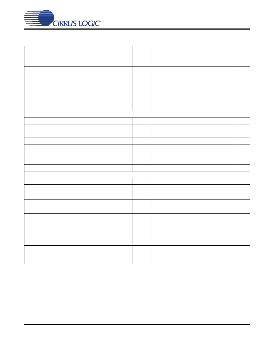
SWITCHING CHARACTERISTICS - SERIAL AUDIO INTERFACE
11. Not all sample rates are supported for all clock ratios. See table
for supported ratios and frequencies.
12. In Internal SCLK Mode, the duty cycle must be 50%
±
1/2 MCLK period.
13. The SCLK / LRCK ratio may be either 32, 48, 64, or 72. This ratio depends on data format and
MCLK/LRCK ratio. (See
)
Parameters
Symbol Min
Typ
Max
Units
MCLK Frequency
0.512
-
50
MHz
MCLK Duty Cycle
45
-
55
%
Input Sample Rate All MCLK/LRCK ratios combined
256x, 384x, 1024x
256x, 384x
512x, 768x
1152x
128x, 192x
64x, 96x
128x, 192x
Fs
2
2
84
42
30
50
100
168
216
54
134
67
34
108
216
216
kHz
kHz
kHz
kHz
kHz
kHz
kHz
kHz
External SCLK Mode
LRCK Duty Cycle (External SCLK only)
45
50
55
%
SCLK Pulse Width Low
t
sclkl
20
-
-
ns
SCLK Pulse Width High
t
sclkh
20
-
-
ns
SCLK Duty Cycle
45
50
55
%
SCLK rising to LRCK edge delay
t
slrd
20
-
-
ns
SCLK rising to LRCK edge setup time
t
slrs
20
-
-
ns
SDIN valid to SCLK rising setup time
t
sdlrs
20
-
-
ns
SCLK rising to SDIN hold time
t
sdh
20
-
-
ns
Internal SCLK Mode
LRCK Duty Cycle (Internal SCLK only)
-
50
-
%
SCLK Period
t
sclkw
-
-
ns
SCLK rising to LRCK edge
t
sclkr
-
-
s
SDIN valid to SCLK rising setup time
t
sdlrs
-
-
ns
SCLK rising to SDIN hold time
MCLK / LRCK =1152, 1024, 512, 256, 128, or 64
t
sdh
-
-
ns
SCLK rising to SDIN hold time
MCLK / LRCK = 768, 384, 192, or 96
t
sdh
-
-
ns
10
9
SCLK
----------------
tsclkw
2
------------------
10
9
512
Fs
----------------------
10
+
10
9
512
Fs
----------------------
15
+
10
9
384
Fs
----------------------
15
+