5 initialization and power-down, Figure 12 – Cirrus Logic CS4361 User Manual
Page 15
15
CS4361
Confidential Draft
9/30/11
4.5
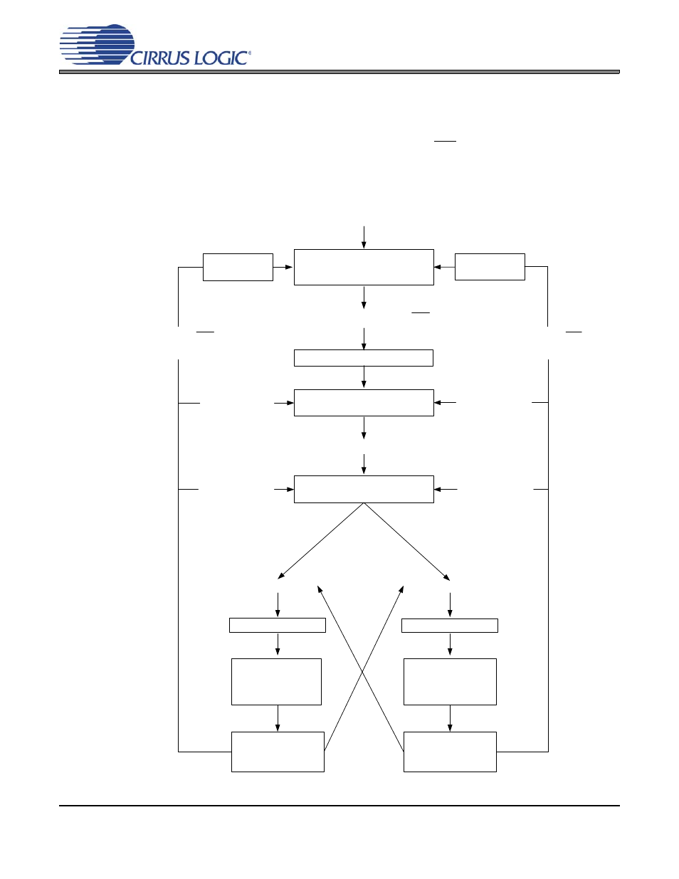
Initialization and Power-Down
The initialization and power-down sequence flow chart is shown in
. The CS4361 enters the pow-
er-down state upon initial power-up. The interpolation filters and delta-sigma modulators are reset, and the
internal voltage reference, multi-bit digital-to-analog converters, and switched-capacitor low-pass filters are
powered down. The device will remain in the Power-Down Mode until RST is released and MCLK and LRCK
are present. Once MCLK and LRCK are detected, MCLK occurrences are counted over one LRCK period
to determine the MCLK/LRCK frequency ratio. Power is then applied to the internal voltage reference. Final-
ly, power is applied to the D/A converters and switched-capacitor filters, and the analog outputs will ramp to
the quiescent voltage, VQ.
USER: Apply Power
Wait State
USER: Apply LRCK and MCLK
MCLK/LRCK Ratio Detection
USER: Applied SCLK
USER: Remove
LRCK
USER: change
MCLK/LRCK ratio
SCLK mode = internal
SCLK mode = external
Normal Operation
De-emphasis
available
Analog Output
is Generated
Normal Operation
De-emphasis
not available
Analog Output
is Generated
USER: change
MCLK/LRCK ratio
USER: Apply RST
or remove MCLK
USER: Remove
LRCK
USER: Apply RST
or remove MCLK
USER: Apply MCLK, release RST
Power-Down State
VQ and outputs low
VQ and outputs
ramp down
VQ and outputs
ramp down
VQ and outputs ramp up
USER: No SCLK
Figure 12. CS4361 Initialization and Power-Down Sequence