Note 10), Cs4353 – Cirrus Logic CS4353 User Manual
Page 8
8
DS803F3
CS4353
9.
SDIN = 0. AOUT_REF input test signal is a 60 Hz, 50 mVpp sine wave. Measured by applying the test
signal into the AOUT_REF pin and measuring the resulting output amplitude on the AOUTx pin. Spec-
ification calculated by:
10. Applying a DC voltage on the AOUT_REF pin will cause a DC offset on the DAC output. See
for more information.
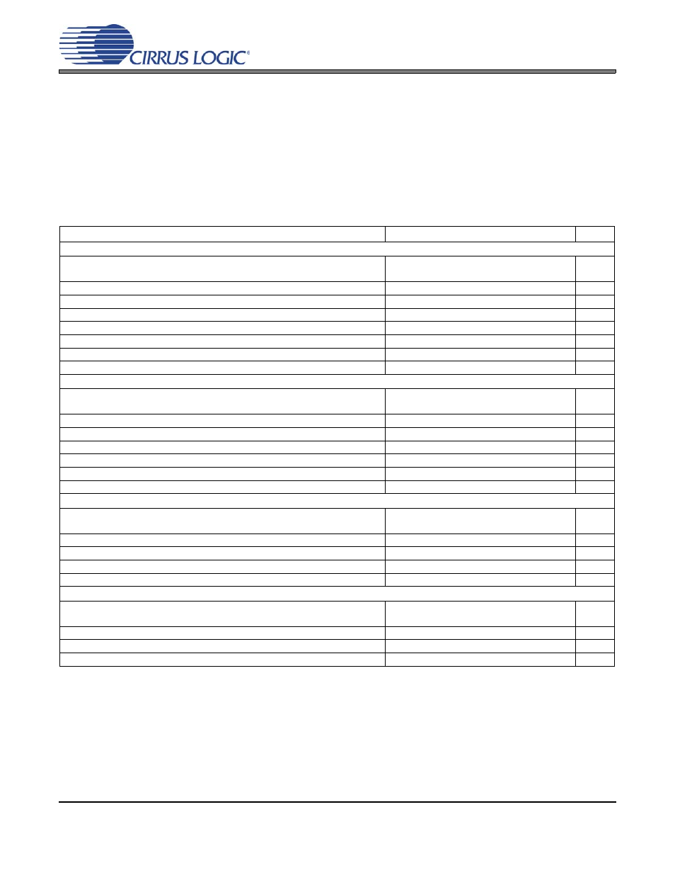
COMBINED INTERPOLATION & ON-CHIP ANALOG FILTER RESPONSE
The filter characteristics have been normalized to the sample rate (Fs) and can be referenced to the desired sam-
ple rate by multiplying the given characteristic by Fs.
Notes: 11. Response is clock-dependent and will scale with Fs.
12. For Single- and Double-Speed Mode, the Measurement Bandwidth is from stopband to 3 Fs.
For Quad-Speed Mode, the Measurement Bandwidth is from stopband to 1.34 Fs.
13. De-emphasis is available only in Single-Speed Mode.
14. Amplitude vs. Frequency plots of this data are available in
“Digital Filter Response Plots” on page 21
.
Parameter
Min Typ
Max
Unit
Single-Speed Mode - 48 kHz
to -0.01 dB corner
to -3 dB corner
0
0
-
-
.454
.499
Fs
Fs
Frequency Response 10 Hz to 20 kHz
-0.01
-
+0.01
dB
StopBand
0.547
-
-
Fs
StopBand Attenuation
102
-
-
dB
Total Group Delay (Fs = Sample Rate)
-
9.4/Fs
-
s
Intra-channel Phase Deviation
-
-
±0.56/Fs
s
Inter-channel Phase Deviation
-
-
0
s
De-emphasis Error
(Relative to 1 kHz)
Fs = 44.1 kHz
-
-
±0.14
dB
Double-Speed Mode - 96 kHz
to -0.01 dB corner
to -3 dB corner
0
0
-
-
.430
.499
Fs
Fs
Frequency Response 10 Hz to 20 kHz
-0.01
-
0.01
dB
StopBand
.583
-
-
Fs
StopBand Attenuation
80
-
-
dB
Total Group Delay (Fs = Sample Rate)
-
4.6/Fs
-
s
Intra-channel Phase Deviation
-
-
±0.03/Fs
s
Inter-channel Phase Deviation
-
-
0
s
Quad-Speed Mode - 192 kHz
to -0.01 dB corner
to -3 dB corner
0
0
-
-
.105
.490
Fs
Fs
Frequency Response 10 Hz to 20 kHz
-0.01
-
0.01
dB
StopBand
.635
-
-
Fs
StopBand Attenuation
90
-
-
dB
Total Group Delay (Fs = Sample Rate)
-
4.7/Fs
-
s
High-Pass Filter Characteristics
to -0.05 dB corner
to -3 dB corner
9.00x10
-5
9.74x10
-6
-
-
-
-
Fs
Fs
Passband Ripple
-
-
0.01
dB
Phase Deviation @ 20 Hz
-
-
1.34
Deg
Filter Settling Time (input signal goes to 95% of its final value)
-
5x10
4
/Fs
-
s
AOR
dB
20 log
10
AOUT_REF
AOUT_REF
AOUTx
–
---------------------------------------------------------
=