Digital interface characteristics, Internal power-on reset threshold voltages, Figure 2. power-on reset threshold sequence – Cirrus Logic CS4353 User Manual
Page 10: Figure 2.power-on reset threshold sequence, Cs4353 digital interface characteristics
10
DS803F3
CS4353
DIGITAL INTERFACE CHARACTERISTICS
Test conditions (unless otherwise specified): AGND = DGND = CPGND = 0 V; all voltages with respect to ground.
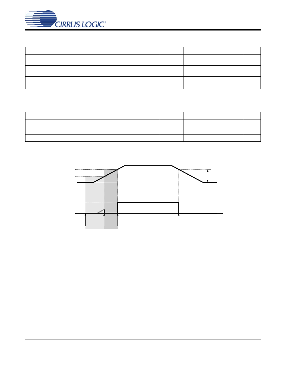
INTERNAL POWER-ON RESET THRESHOLD VOLTAGES
Test conditions (unless otherwise specified): AGND = DGND = CPGND = 0 V; all voltages with respect to ground.
Figure 2. Power-on Reset Threshold Sequence
Parameters
Symbol Min Typ
Max
Units
High-Level Input Voltage
1.2 V <
VL 3.3 V
0.9 V
VL 1.2 V
V
IH
V
IH
0.7xVL
0.9xVL
-
-
-
-
V
V
Low-Level Input Voltage
1.2 V <
VL 3.3 V
0.9 V
VL 1.2 V
V
IL
V
IL
-
-
-
-
0.3xVL
0.1xVL
V
V
Input Leakage Current
I
in
-
-
±10
A
Input Capacitance
-
8
-
pF
Parameters
Symbol
Min
Typ
Max
Units
Internal Reset Asserted at Power-On
V
on1
-
1.00
-
V
Internal Reset Released at Power-On
V
on2
-
2.36
-
V
Internal Reset Asserted at Power-Off
V
off
-
2.22
-
V
VCP
V
on2
V
on1
V
off
DGND
HI
LO
No Power
reset
undefined
reset
active
DAC
Ready
reset
active
reset
(internal)