Cs4299, Analog hardware description, 1 analog inputs – Cirrus Logic CS4299 User Manual
Page 36: 1 line-level inputs, 2 cd input, Cd in- put signal
CS4299
36
6. ANALOG HARDWARE
DESCRIPTION
The analog line-level input hardware consists of
four stereo inputs (LINE_IN_L/R, CD_L/GND/R,
VIDEO_L/R, and AUX_L/R), two selectable
mono microphone inputs (MIC1 and MIC2), and
two mono inputs (PC_BEEP and PHONE). The an-
alog line-level output hardware consists of a mono
output (MONO_OUT), and dual stereo line outputs
(LINE_OUT_L/R and ALT_LINE_OUT_L/R).
This section describes the analog hardware needed
to interface with these pins. The designs presented
in this section comply with specifications detailed
in Chapter 17 of the Microsoft
PC Design Guide-
lines [7] (referred to as PC 99). For EMI reduction
techniques refer to the application note N165:
CS4297A/CS4299 EMI Reduction Techniques [5].
6.1
Analog Inputs
All analog inputs to the CS4299, including
CD_GND, should be capacitively coupled to the
input pins. Unused analog inputs should be tied to-
gether and connected through a capacitor to analog
ground or tied to the Vrefout pin directly. The max-
imum allowed voltage for analog inputs, except the
microphone input, is 1 V
RMS
. For the microphone
input the maximum allowed voltage depends on the
selected boost setting.
6.1.1
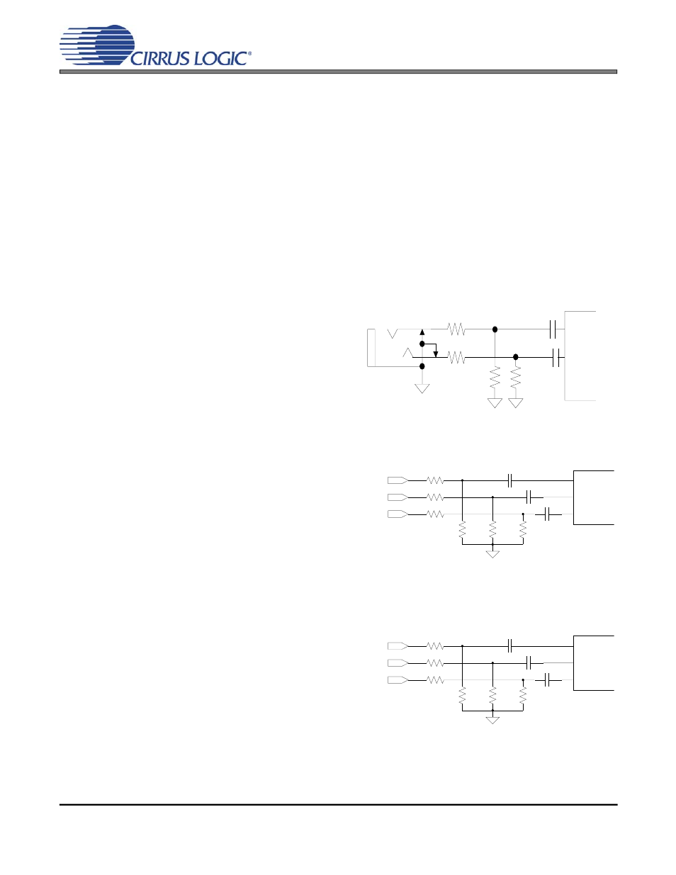
Line-Level Inputs
Figure 10 shows circuitry for a line-level stereo in-
put. Replicate this circuit for the Line, Video and
Aux inputs. This design attenuates the input by
6 dB, bringing the signal from the PC 99 specified
2 V
RMS
, to the CS4299 maximum allowed 1 V
RMS
.
6.1.2
CD Input
The CD line-level input has an extra pin,
CD_GND, providing a pseudo-differential input
for both CD_L and CD_R. This pin takes the
common-mode noise out of the CD inputs when
connected to the CD analog source ground. Follow-
ing the reference designs in Figure 11 and
Figure 12 provides extra attenuation of common
mode noise coming from the CD-ROM drive,
thereby producing a higher quality signal. One per-
cent resistors are recommended since closely
matched resistor values provide better com-
mon-mode attenuation of unwanted signals. The
circuit shown in Figure 11 can be used to attenuate
a 2 V
RMS
CD input signal by 6 dB. The circuit
shown in Figure 12 can be used for a 1 V
RMS
CD in-
put signal.
6.8 k
Ω
6.8 k
Ω
1.0
µF
1.0
µF
R
L
6.8 k
Ω
6.8 k
Ω
Figure 10. Line Input (Replicate for Video and Aux)
(All resistors 1%)
6.8 k
Ω
CD_L
CD_COM
CD_R
1.0
µF
CD_L
CD_R
CD_GND
6.8 k
Ω
1.0
µF
3.4 k
Ω
6.8 k
Ω
2.2
µF
3.4 k
Ω
6.8 k
Ω
AGND
Figure 11. Differential 2 V
RMS
CD Input
100
Ω
CD_L
CD_COM
CD_R
1.0
µF
CD_L
CD_R
CD_GND
100
Ω
1.0
µF
100
Ω
47 k
Ω
2.2
µF
47 k
Ω
47 k
Ω
AGND
Figure 12. Differential 1 V
RMS
CD Input
36
DS319PP6
CS4299