Cdb connectors, switches, indicators and jumpers, Table 14. connectors and switches, Table 15. jumpers and indicators – Cirrus Logic CDB4270 User Manual
Page 26: Cdb4270
26
DS686DB3
CDB4270
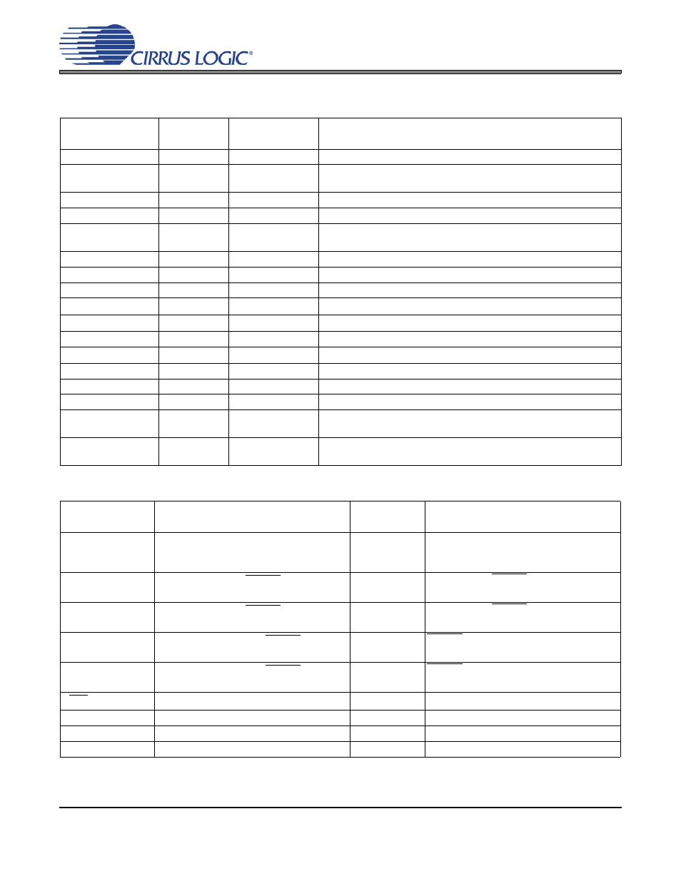
7. CDB CONNECTORS, SWITCHES, INDICATORS AND JUMPERS
CONNECTOR,
SWITCH
Reference
Designator INPUT/OUTPUT
SIGNAL PRESENT
+5V
J1
Input
+5.0 V Power Supply
CLK/DATA CON-
TROL
S1
Input
HW Mode Clock/Data Routing Control Dip Switch
HW MODE CONFIG
S2
Input
HW Mode CS4270 Mode Control Switch
GND
J2
Input
Ground Reference
SPDIF OPTICAL
OUT
OPT2
Output
CS8406 digital audio output via optical cable
SPDIF COAX OUT
J7
Output
CS8406 digital audio output via coaxial cable
SPDIF OPTICAL IN
OPT1
Input
CS8416 digital audio input via optical cable
SPDIF COAX IN
J5
Input
CS8416 digital audio input via coaxial cable
RS232
J16
Input/Output
Serial connection to PC for SPI /
I²C
Control Port signals
USB
J15
Input/Output
USB connection to PC for SPI /
I²C
Control Port signals
DSP HEADER
J9
Input/Output
I/O for Clocks & Data
SERIAL CONTROL
J10
Input/Output
I/O for external SPI /
I²C
Control Port signals
MICRO C2 HEADER
J14
Input/Output
I/O for programming the micro controller (U21)
FPGA JTAG
J12
Input/Output
I/O for programming the FPGA (U11)
MICRO RESET
S4
Input
Reset for the micro controller (U21)
AINA
AINB
J13
J11
Input
RCA phono jacks for analog inputs
AOUTA
AOUTB
J6
J4
Output
RCA phono jacks for analog outputs
Table 14. Connectors and Switches
JUMPER/
INDICATOR
PURPOSE
POSITION/
REF DES
FUNCTION SELECTED/INDICATION
CONTROL
JUMPERS
SPI/I²C control Internal or external select
*J10, pins 1-2
J10, none
*Normal I²C/SPI Operation
Connect to pins 2 (control) and 3 (gnd) for
external control
MUTEA
JUMPERS
Selects between MUTEA Enable and
MUTEA LED Indicator Enable
*J8, pins 1-2
J8, pins 2-3
* MUTEA Enable
MUTEA LED Enable
MUTEB
JUMPERS
Selects between MUTEB Enable and
MUTEB LED Indicator Enable
*J3, pins 1-2
J3, pins 2-3
* MUTEB Enable
MUTEB LED Enable
MUTEA LED
Indicates that CS4270 MUTEA signal is
present
D3
MUTEA from CS4270 is present when LED
is on
MUTEB LED
Indicates that CS4270 MUTEB signal is
present
D1
MUTEB from CS4270 is present when LED
is on
INIT INDICATOR
Indicates FPGA program INIT
D5
FPGA is being programmed when on
DONE
Indicates FPGA program complete
D4
FPGA has been programmed when on
RCVR ERROR
Indicates CS8416 Data Receive Error
D2
Indicates Data Receive Error when on
USB PRESENT
Indicates USB Connection
D7
Indicates USB connection when on
*Default factory settings
Table 15. Jumpers and Indicators