Hardware mode, Fpga gui register description, 1 fpga register quick reference – Cirrus Logic CDB4270 User Manual
Page 18: Hardware mode 5. fpga gui register description, Fpga gui register description” on, Hardware, Fpga gui, Register description, Fpga, Gui register description
18
DS686DB3
CDB4270
4. HARDWARE MODE
When the Flex GUI is not running on a PC or when the USB or serial port cables are not connected to the CDB4270
from the PC, the board is automatically in Hardware Control Mode. When in this control mode, dip switches S1 and
S2 control the board’s functionality. Note: Hardware Mode controls are a subset of Software Mode controls, and
some FPGA or CS4270 register bits cannot be changed in Hardware Mode. See
of this document for a complete description of the Hardware Mode settings.
5. FPGA GUI REGISTER DESCRIPTION
As mentioned previously, the CS4270 and FPGA registers are directly accessible in Software Mode within the Flex
GUI. In Hardware Mode, the FPGA registers control all board functions. The FPGA register descriptions for both
modes are described below. For a description of the CS4270 registers, see the CS4270 data sheet.
5.1
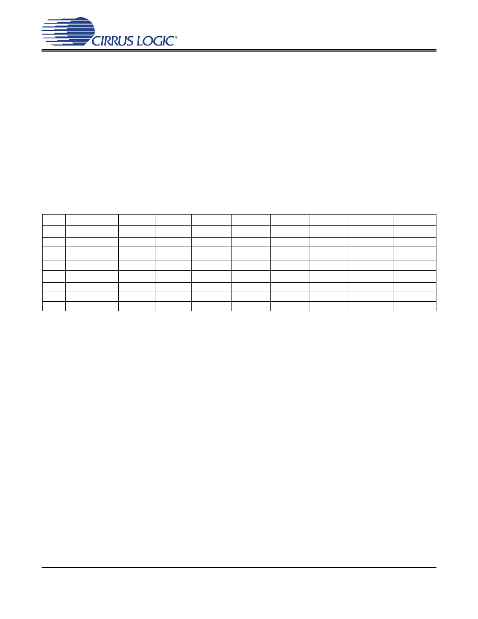
FPGA REGISTER QUICK REFERENCE
The table below shows the register names and their associated default values.
Note:
Default “power on” bit states are shown.
Addr
Function
7
6
5
4
3
2
1
0
00h
Code Rev. ID
REV.7
REV.6
REV.5
REV.4
REV.3
REV.2
REV.1
REV.0
0
0
0
1
0
1
1
1
01h
SDIO/CLK/SW/HW
Control
SDIO.1
SDIO.0
Reserved
MCLK
DUT_SDIO.1
DUT_SDIO.0
SUB_CK.1
SUB_CK.0
0
0
0
1
0
0
0
0
02h
CS8406 Control
TXCLK.1
TXCLK.0
Reserved
TX_M/S
TX_FMT
Reserved
TXSDIO.1
TXSDIO.0
0
0
0
0
0
0
0
1
03h
CS8416 Control
Reserved
RXCLK
Reserved
RX_M/S
RX_FMT
Reserved
Reserved
Reserved
0
0
0
0
0
0
0
0