2 omck system clock mode, Table 1. common omck clock frequencies, 3 master mode – Cirrus Logic CS42528 User Manual
Page 25: Table 2. common pll output clock frequencies, 4 slave mode, Table 2
DS586F2
25
CS42528
4.5.2
OMCK System Clock Mode
A special clock-switching mode is available that allows the clock that is input through the OMCK pin to be
used as the internal master clock. This feature is controlled by the SW_CTRLx bits in register
trol (address 06h)” on page 52
. An advanced auto-switching mode is also implemented to maintain mas-
ter clock functionality. The clock auto-switching mode allows the clock input through OMCK to be used as
a clock in the system without any disruption when the PLL loses lock, for example, when the input is re-
moved from the receiver. This clock-switching is done glitch-free. A clock adhering to the specifications
detailed in the Switching Characteristics table on
must be applied to the OMCK pin at all times
that the FRC_PLL_LK bit is set to ‘0’ (See
“Force PLL Lock (FRC_PLL_LK)” on page 53
).
4.5.3
Master Mode
In Master Mode, the serial interface timings are derived from an external clock attached to OMCK or from
the output of the PLL with an input reference to either the S/PDIF Receiver recovered clock or the SAI_L-
RCK input from the Serial Audio Interface Port. Master clock selection and operation is configured with
the SW_CTRL1:0 bits in the Clock Control Register (See
“Clock Control (address 06h)” on page 52
).The
supported PLL output frequencies are shown in Table
below.
4.5.4
Slave Mode
In Slave Mode, CX_LRCK, CX_SCLK and/or SAI_LRCK, SAI_SCLK operate as inputs. The Left/Right
clock signal must be equal to the sample rate, Fs, and must be synchronously derived from the supplied
master clock, OMCK, or the output of the PLL. The serial bit clock, CX_SCLK and/or SAI_SCLK, must be
synchronously derived from the master clock and be equal to 128x, 64x, 48x or 32x Fs, depending on the
interface format selected and desired speed mode.
When the device is clocked from OMCK, the frequency of OMCK must be at least twice the frequency of
the fastest Slave Mode, SCLK. For example, if both serial ports are in Slave Mode with one SCLK running
at 32x Fs and the other at 64x Fs, the slowest OMCK signal that can be used to clock the device is
128x Fs.
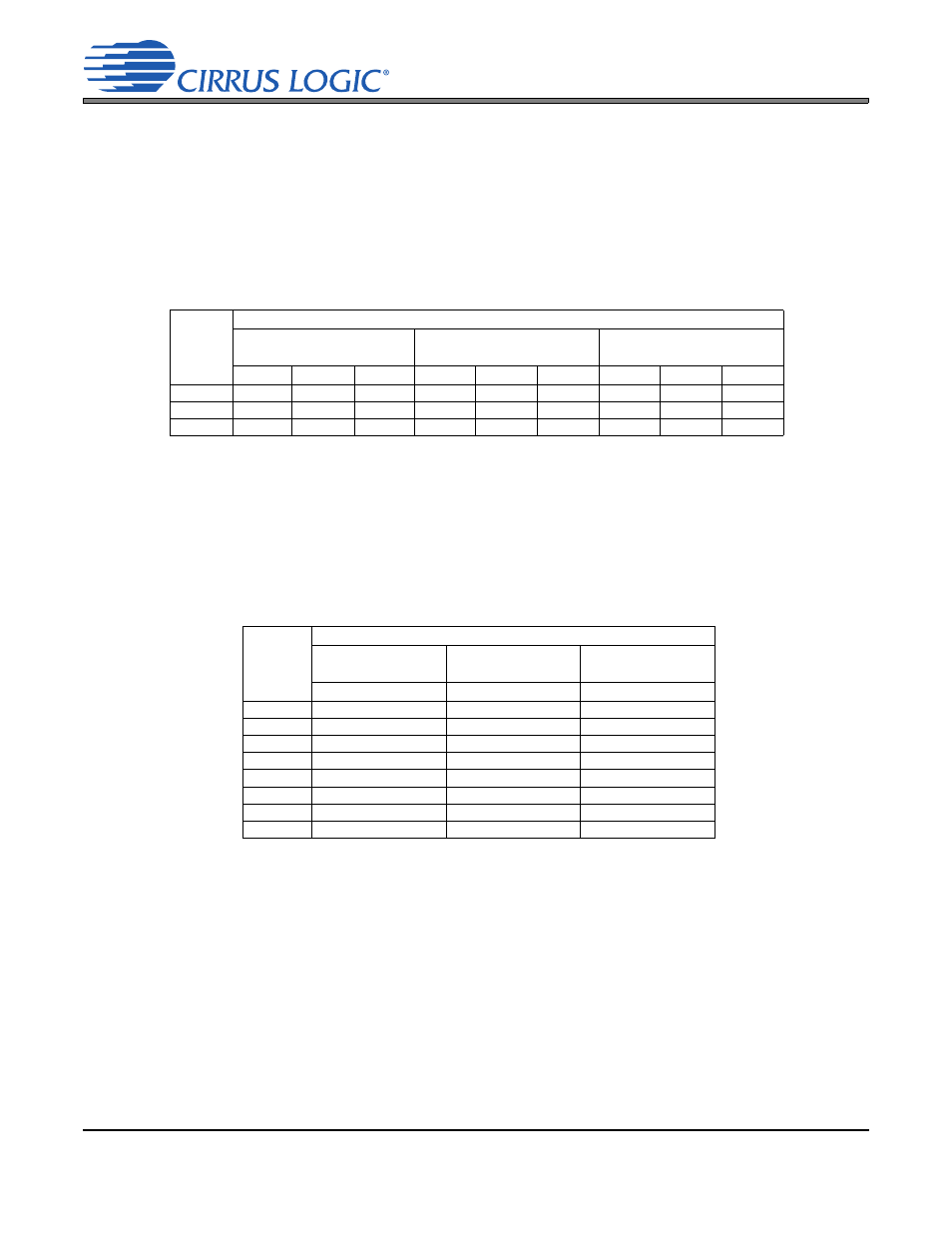
Sample
Rate
(kHz)
OMCK (MHz)
Single-Speed
(4 to 50 kHz)
Double-Speed
(50 to 100 kHz)
Quad-Speed
(100 to 192 kHz)
256x
384x
512x
128x
192x
256x
64x
96x
128x
48
12.2880 18.4320 24.5760
-
-
-
-
-
-
96
-
-
-
12.2880 18.4320 24.5760
-
-
-
192
-
-
-
-
-
-
12.2880 18.4320 24.5760
Table 1. Common OMCK Clock Frequencies
Sample
Rate
(kHz)
PLL Output (MHz)
Single Speed
(4 to 50 kHz)
Double Speed
(50 to 100 kHz)
Quad Speed
(100 to 192 kHz)
256x
256x
256x
32
8.1920
-
-
44.1
11.2896
-
-
48
12.2880
-
-
64
-
16.3840
-
88.2
-
22.5792
-
96
-
24.5760
-
176.4
-
-
45.1584
192
-
-
49.1520
Table 2. Common PLL Output Clock Frequencies