3 digital volume and mute control, 4 atapi specification – Cirrus Logic CS42528 User Manual
Page 22
22
DS586F2
CS42528
4.3.3
Digital Volume and Mute Control
Each DAC’s output level is controlled via the Volume Control registers operating over the range of 0 to
-127 dB attenuation with 0.5 dB resolution. See
“Volume Control (addresses 0Fh, 10h, 11h, 12h, 13h,
. Volume control changes are programmable to ramp in increments of
0.125 dB at the rate controlled by the SZC[1:0] bits in the Digital Volume Control register. See
Transition Control (address 0Dh)” on page 56
.
Each output can be independently muted via mute control bits in the register
. When enabled, each XX_MUTE bit attenuates the corresponding DAC to its maximum
value (-127 dB). When the XX_MUTE bit is disabled, the corresponding DAC returns to the attenuation
level set in the Volume Control register. The attenuation is ramped up and down at the rate specified by
the SZC[1:0] bits.
The Mute Control pin, MUTEC, is typically connected to an external mute control circuit. The Mute Control
pin outputs high impedance during Power-Up or in Power-Down Mode by setting the PDN bit in the reg-
ister
“Power Control (address 02h)” on page 46
to a ‘1’. Once out of Power-Down Mode, the pin can be
controlled by the user via the control port, or automatically asserted high when zero data is present on all
DAC inputs, or when serial port clock errors are present. To prevent large transients on the output, it is
desirable to mute the DAC outputs before the Mute Control pin is asserted. Please see the MUTEC pin
in the Pin Descriptions section for more information.
Each of the RXP1/GPO1-RXP7/GPO7 can be programmed to provide a hardware MUTE signal to indi-
vidual circuits. When not used as an S/PDIF input, each pin can be programmed as an output, with spe-
cific muting capabilities as defined by the function bits in the register
“RXP/General-Purpose Pin Control
(addresses 29h to 2Fh)” on page 69
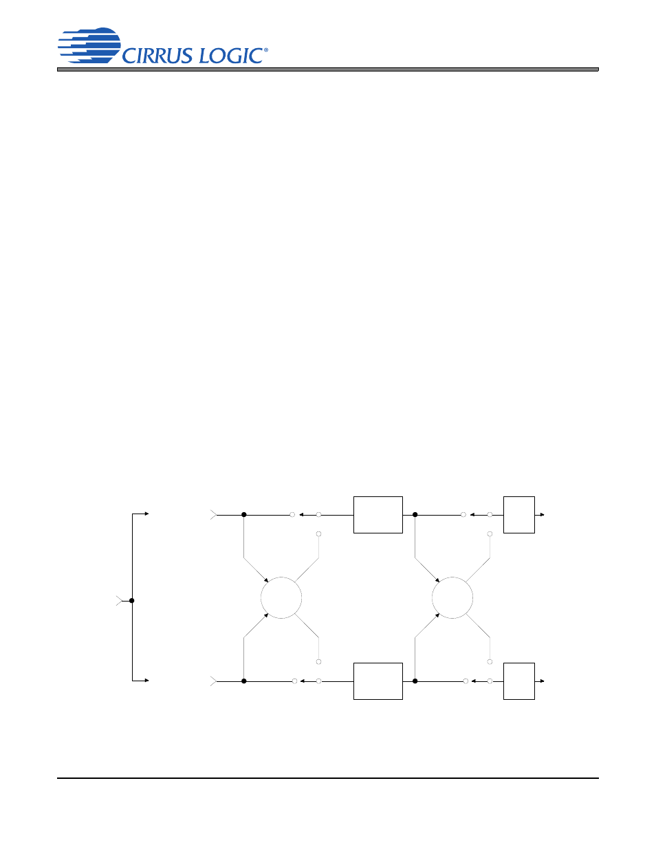
4.3.4
ATAPI Specification
The CS42528 implements the channel-mixing functions of the ATAPI CD-ROM specification. The
ATAPI functions are applied per A-B pair. Refer to
for additional infor-
mation.
A Channel
Volume
Control
AOUTAx
AOUTBx
Left Channel
Audio Data
Right Channel
Audio Data
B Channel
Volume
Control
MUTE
MUTE
CX_SDINx
Figure 8. ATAPI Block Diagram (x = channel pair 1, 2, 3, 4)