An300, 100 db, 60 db – Cirrus Logic AN300 REV1 User Manual
Page 6
6
AN300REV1
AN300
operating current. But there is another approach to achieve low noise in a CMOS amplifier. That is to modulate
(chop) the input signal and amplify the signal as an AC signal at a frequency that is significantly higher than the 1/f
corner frequency. If the chopping is performed at a higher frequency where the spot noise is low, the noise floor will
be dictated by the noise value at the chopping frequency. The chopper-stabilized amplifiers from Cirrus Logic use
this approach. Most chopper amplifiers from other manufacturers chop at lower frequencies, where the spot noise
is higher. Some choppers even chop in the region of the rising 1/f noise.
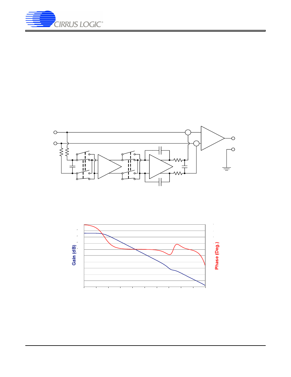
Cirrus Logic manufactures amplifiers having different chopper-stabilized architectures. The CS3003/4/13/14 ampli-
fiers are similar to the architecture shown in
Figure 1
, but with the design optimized for silicon implementation. A
block diagram of these devices is illustrated in
Figure 7
. The chopping frequency in the CS3003/4 devices is at
about 150 kHz. The CS3013/14 chopping frequency is at about 125 kHz. The filter at the output of the chopping
amplifier is on chip where capacitor sizes are limited. A higher chopping clock is more easily filtered when capacitor
size of the filter must be a small value. These amplifiers combine chopper-stabilized input performance with rail-to-
rail input and rail-to-rail output capability. Even though these amplifiers are chopped, they can be used for audio-
bandwidth applications because no chopping clock residuals exist below 100 kHz.
Figure 7. Block Diagram of Cirrus Logic’s Chopper-stabilized Amplifier, CS3003/04/13/14
Figure 8
illustrates the open loop gain and phase of the CS3003/04 amplifiers. One can readily see from the plot
that the transition point between the chopper amplifier signal path and the high frequency signal path cross over
near 20 kHz.
Figure 8. CS3003/04 Gain & Phase vs. Frequency
Recall that the gains of the amplifier stages add together (in dB). The combination requires careful design to main-
tain stability and to achieve the proper frequency crossover between the two signal paths. But the result is an
amplifier with very high open loop gain.
The CS3001/2/11/12 amplifiers differ architecturally from the CS3003/04/13/14 devices. The CS3001/2/11/12
amplifiers have more signal paths than the typical chopper-stabilized amplifier.
Figure 9
illustrates the signal paths
E
in
E
out
≈ 100 dB
Σ
≈ 60 dB
Σ
-20
0
20
40
60
80
100
120
140
160
180
Frequency (Hz)
-180
-135
-90
-45
0
45
90
135
180
225
270
0.001
0.1
10
1k
100k
10M
0.01
1
100
10k
1M