Cirrus Logic AN300 REV1 User Manual
An300, Introduction
Copyright
© Cirrus Logic, Inc. 2008
(All Rights Reserved)
CS3001/2/11/12 & CS3003/4/13/14 Chopper-stabilized
Operational Amplifiers
Jerome E. Johnston
1. INTRODUCTION
Cirrus Logic offers a variety of low-voltage CMOS chopper-stabilized amplifiers.
The chopper-stabilized amplifiers designed at Cirrus Logic are unique. These amplifiers offer performance benefits
that combine the best features of bipolar amplifiers with the best features of chopper amplifiers. The intent of this
application note is to understand Cirrus Logic's unique technology and to see how it can be applied in various mea-
surement applications. But before the applications are discussed, the following provides a brief overview of the con-
cepts involved in a chopper-stabilized amplifier.
2. CHOPPER AMPLIFIER AND CHOPPER-STABILIZED AMPLIFIER BASICS
Not everyone is familiar with chopper amplifiers and chopper-stabilized amplifiers. A look back at some history can
help us understand how the chopper-stabilized amplifier operates.
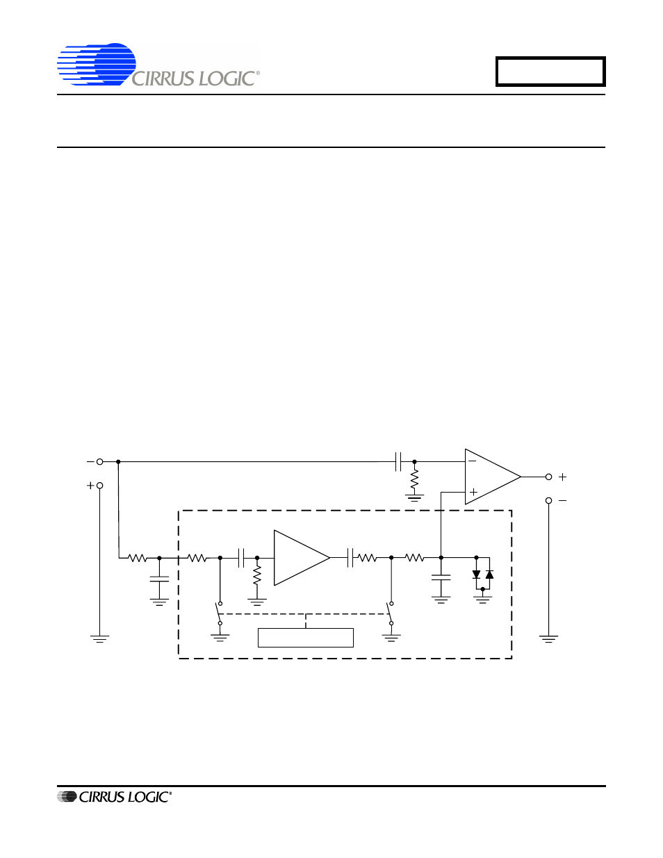
Figure 1
illustrates the block diagram of a chopper-stabilized amplifier. A chopper-stabilized amplifier is a DC am-
plifier whose offset is stabilized by a chopping amplifier. The basic amplifier diagram in
Figure 1
is called the Gold-
berg configuration, named after E. A. Goldberg, an engineer who designed and patented electron tube-based,
chopper-stabilized amplifiers for RCA (Radio Corporation of America) in the 1940s and 1950s.
Figure 1. Basic Chopper-stabilized Amplifier Block Diagram
The Goldberg configuration was later used in a transistorized chopper-stabilized amplifier designed and sold
by Zeltex Corporation in the 1970s for about $125 (US). The Zeltex chopper-stabilized amplifier follows the basic
block diagram of
Figure 1
. The input signal (e
in
) at the inverting input of the amplifier travels through two different
signal paths. (The Goldberg configuration amplifier could only be used as an inverting amplifier.) The first path is
into Amplifier #1 of
Figure 1
. Components R1-C1 act as a high-pass filter that prevents the DC portion of the signal
from passing directly into Amplifier #1. The second path is through a low-pass filter composed of R2 and C2. The
R2-C2 filter limits the bandwidth of the signal to be chopped by the chopper amplifier. Amplifier #2 is the chopper
AMP2
AMP1
e
in
R4
C3
R6
R5
C2
R3
R2
R1
C1
C4
S2
S1
Oscillator
AC Amplifier (Chopper)
DC Amplifier
e
out
C5
Low-pass
Filter
AN300
JUL
‘
08
AN300REV1