An300 – Cirrus Logic AN300 REV1 User Manual
Page 5
AN300REV1
5
AN300
As mentioned previously, bipolar transistors have long dominated the world of operational amplifiers. Let's look at
some of the differences of parameters of bipolar transistors versus MOS transistors. Understanding the differ-
ences between these two technologies can help explain some of the constraints on the architectural choices used
in the design of CMOS chopper-stabilized amplifiers.
The construction of bipolar transistors and MOS transistors are very different. The difference in construction results
in large differences in some performance parameters. One area of significant difference is noise performance.
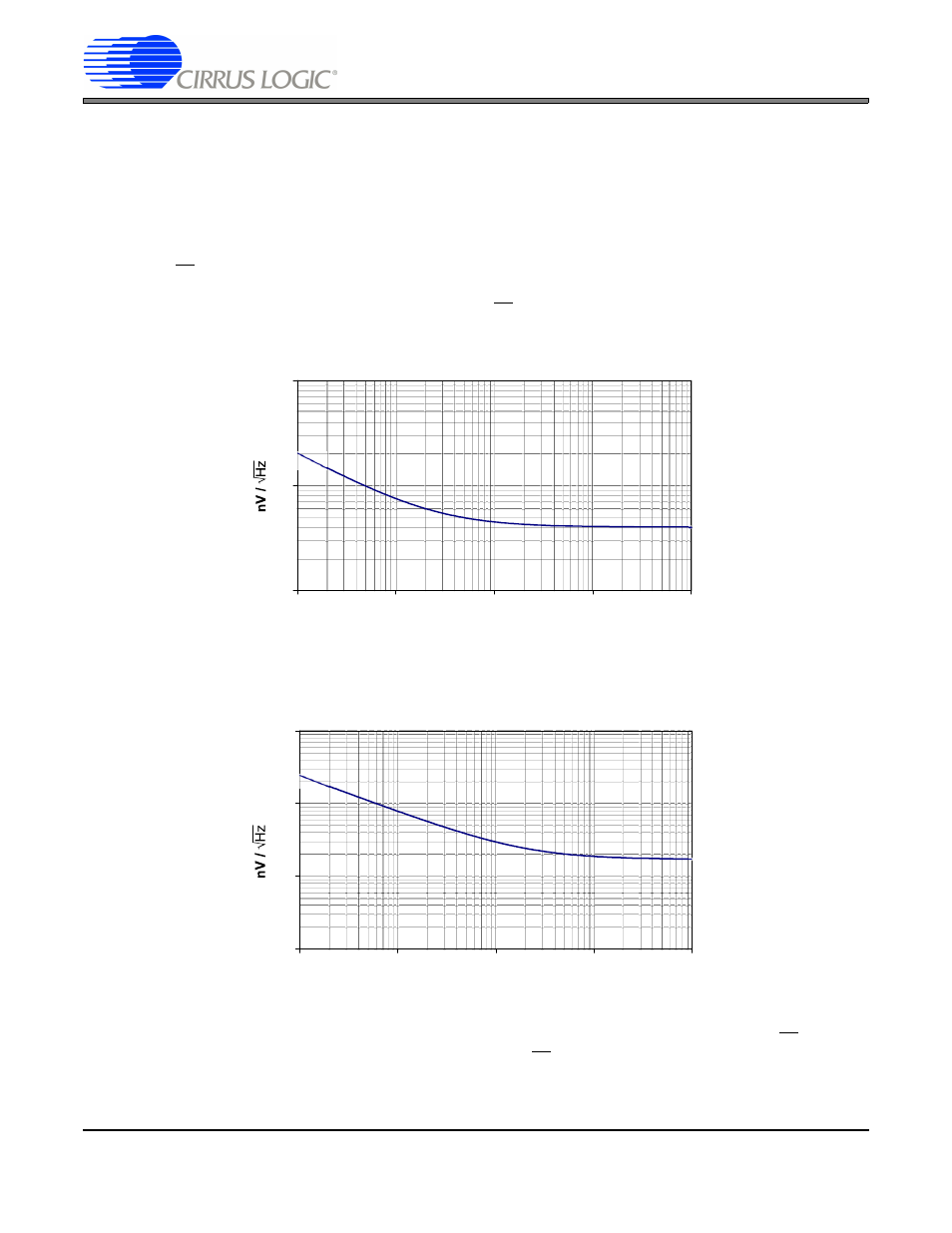
Figure 5
illustrates a noise plot for a bipolar transistor. This hypothetical but typical device exhibits a spot noise at 1
kHz of 4 nV/
√Hz with a 1/f corner at 2.5 Hz. Because of the difference in construction, a MOS transistor would have
difficulty achieving this level of noise performance.
Figure 6
illustrates a noise plot for a hypothetical but typical
MOS transistor. This device exhibits a spot noise of 17 nV/
√Hz at 50 kHz with a 1/f corner at 2000 Hz.
Figure 5. Noise Performance Plot for a Bipolar Transistor
Figure 6. Noise Performance Plot for a MOS Transistor
Note from
Figure 5
that the magnitude of the noise of the bipolar transistor at 0.1 Hz is about 20 nV/
√Hz. The spot
noise in the example MOS transistor does not match this 20 nV/
√Hz value until the frequency for the MOS transis-
tor is at about 5 kHz. A MOS transistor can be designed to achieve a lower spot noise and a lower 1/f corner fre-
quency than what is shown in
Figure 6
by significantly increasing the size of the device and by increasing its
Bipolar Transistor Noise
1
10
100
0.1
1
10
100
1k
Frequency (Hz)
MOS Transisitor Noise
1
10
100
1000
10
100
1k
10k
100k
Frequency (Hz)