An300 – Cirrus Logic AN300 REV1 User Manual
Page 3
AN300REV1
3
AN300
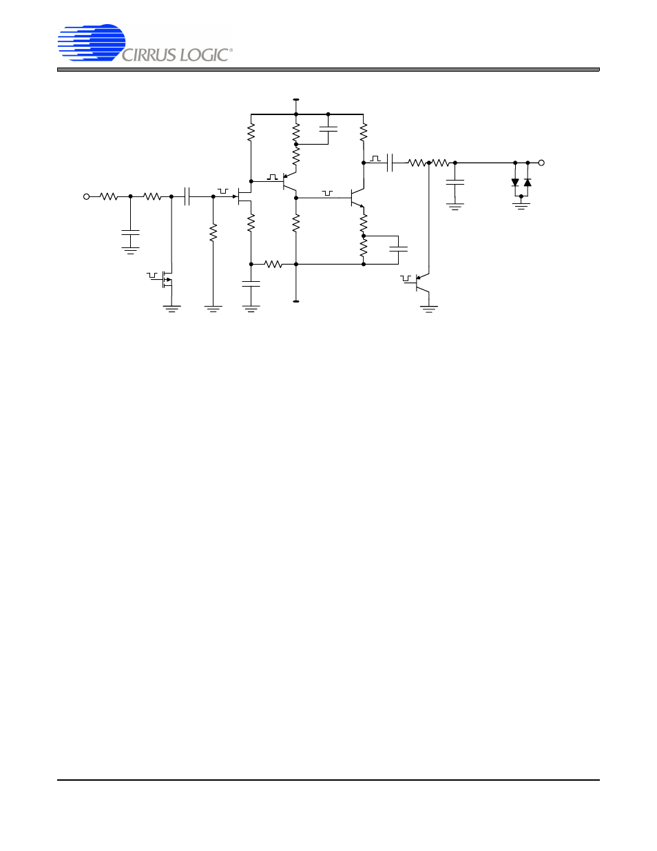
Figure 3. Amplifier 2: Chopper Amplifier Portion of the Zeltex Module
The gain transfer functions of the two amplifiers are multiplied together (or added when stated in dB). The combina-
tion of the two amplifiers produces an open loop gain of about 160 dB. One of the difficulties in the design of the
chopper-stabilized amplifier combination is ensuring stability. The DC performance of the combined amplifiers is dic-
tated by the performance of the chopping input. Input current of the Zeltex amplifier was dominated by charge injec-
tion in the chopping switch at the input of the chopper amplifier. Offset voltage and offset voltage drift of the amplifier
combination was determined by how close the chopping switch at the input of the chopper amplifier approximated
the ideal. The Zeltex amplifier achieved less than 100 pA of input bias current with an offset voltage drift less than
50 nV / °C.
Figure 4
illustrates a typical chopper-stabilized amplifier designed using electron tubes with the amplifiers connected
in the Goldberg configuration. The circuit has the same layout as the block diagram of
Figure 1
. The chopping
switches were mechanical vibrating switches (about 400 Hz) manufactured by Airpax Corporation. The output filter
exhibits an extremely long time constant.
E.A. Goldberg filed a U.S. patent (#2,684,999; assigned to RCA) for a tube-based chopper-stabilized amplifier on
April 28, 1948. But the invention of the chopper architecture itself predates this. J. W. Milnor filed for a U.S. patent
on a chopper amplifier on January 17, 1918.
To DC
R4
2.0M
+15V
-15V
E305
10k
150
2N4299
S2
2N2946
3.9k
2N3565
51k
150
10k
18k
1k
68uF
10k
22uF
22uF
C4
0.033uF
R6
51k
R5
200k
C5
68uF
1N459
1N459
From
Oscillator
R3
100k
C3
4700pF
R2
100k
C2
0.033uF
From
Oscillator
S1
M5079
f
c
= 0.009Hz