Cs1680, If boost output voltage v, And higher regulation range constant k – Cirrus Logic CS1680 User Manual
Page 9: The led output current i, Led output current i
CS1680
DS1055F1
9
voltage to reach the regulation target set by
constant K
Mode1(target)
. If boost output voltage V
BST
is
below the target regulation point or the boost output
voltage is falling, the boost inductor current is increased.
If the boost output voltage is above the target regulation
point, the boost output voltage is rising, or the clamp has
been activated recently the boost current is decreased.
The LED output current is set using a third-order
polynomial of the rectified RMS voltage, computed over
a half-line cycle and filtered to avoid lamp flicker.
Mode2
In Mode2, the CS1680 will detect if the input is a trailing
edge dimmer paired with an electronic transformer or no
dimmer switch paired with an electronic transformer. The
detection algorithm determines its operation based on
the falling edge of the input voltage waveform. To provide
proper dimmer operation, the CS1680 executes the
boost algorithm on the falling edge of the input line
voltage, which will maintain a charge in the dimmer
capacitor. To ensure maximum compatibility with dimmer
components, the device boosts during this falling edge
event using a peak current that must meet a minimum
value.
The boost output voltage V
BST
is measured at the
trailing edge of the rectified voltage every half-line cycle
and compared against the regulation point, which is set
by resistor R
BST
(see Figure 11 on page 10). The
voltage difference, the setting of LED output
current I
OUT
, and the clamp activity are used in the
control loop to modulate the boost turn-on time every
half-line cycle which allows the boost output voltage to
reach the regulation target set by constant
K
Mode2(target)
. If boost output voltage V
BST
is below the
target regulation point or the boost output voltage is
falling, the total turn-on time over a half-line cycle is
increased. If the boost output voltage is above the target
regulation point, the boost output voltage is rising, or the
clamp has been activated recently, the total turn-on time
over a half-line cycle is decreased. The Mode2
algorithm estimates the turn-on time of the transformer
by measuring the conduction angle of the rectified
voltage every half-line cycle. The LED output current is
set based on the output power requirements for a
particular conduction angle by the regulation loop.
Mode3
In Mode3, the CS1680 will detect if the input is a leading
edge dimmer paired with an electronic transformer. The
CS1680 regulates boost output voltage V
BST
while
maintaining the dimmer phase angle. The device
executes a CCM boost algorithm that keeps the boost
peak current inversely proportional to the boost output
voltage. The algorithm attempts to maintain a constant
power while limiting the boost peak current to prevent
saturating the boost inductor.
The Mode1 and Mode2 algorithms use properties of the
input waveform on a cycle-by-cycle basis to determine
the output current, and then adjusts the boost control
parameters to balance the input power with the
requested output power. Unlike the Mode1 and Mode2
algorithms, the Mode3 algorithm leaves the boost
parameters fixed and adjusts the output current to
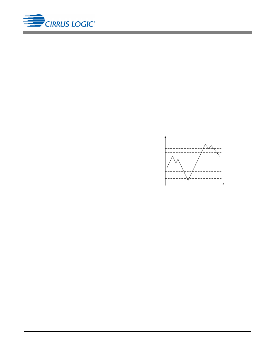
balance input power and output power. As long as boost
output voltage V
BST
remains between the voltage
thresholds set by lower regulation range
constant K
Mode3(low)
and higher regulation range
constant K
Mode3(high)
, the LED output current I
OUT
will
remain constant (see Figure 9).
If the boost output voltage V
BST
rises above the
regulation range high voltage threshold set by
constant K
Mode3(high)
(due to the phase angle of the
dimmer increasing which allows for the first stage to
produce additional power), LED output current I
OUT
is
gradually increased until the boost output voltage V
BST
falls below the regulation range high threshold. The rate
of increase continues to add larger steps as long as
boost output voltage V
BST
stays above the regulation
high threshold. If the boost output voltage continues to
rise and reaches the clamp-on threshold set by
constant K
CLAMP(on)
, the clamp circuit will activate to
dissipate the excess power from the boost output. While
the clamp is on, the LED output current I
OUT
increases
at an accelerated rate.
If the boost output voltage V
BST
falls below the
regulation range low voltage threshold set by
constant K
Mode3(low)
, LED output current I
OUT
is
gradually decreased. The rate of decrease continues to
subtract larger steps as long as the boost output voltage
stays below the regulation range low threshold. If the
Regulation Range High
Regulation Range Low
Accelerated Decrease On
Accelerated Increase On
Accelerated Increase Off
V
BST
u
K
Mode
3(high)
V
BST
u
K
CLAMP(off)
V
BST
u
K
CLAMP(on)
V
BST
u
K
Mode
3(low)
V
BST
u
K
DEC(on)
t
v(t)
Voltage Threshold
Figure 9. Mode3 Output Regulation Algorithm