2 current sense resistor model, 3 zero-current detection, 5 overtemperature protection – Cirrus Logic CS1680 User Manual
Page 12: 1 internal overtemperature protection, 2 external overtemperature protection, Cs1680
CS1680
12
DS1055F1
period T2
BUCK
. The controller then uses the
time TT
BUCK
to determine gate turn-on time.
5.4.2 Current Sense Resistor Model
The digital algorithm ensures monotonic dimming from
5% to 100% of the dimming range with a linear
relationship between the dimming signal and the LED
current. The buck stage is regulated by peak current
control with a 1% external sense resistor R
BUCK(Sense)
connected to the BUCKSENSE pin. Buck peak current
I
BUCKPK(max)
is calculated using Equation 7:
Overcurrent protection (OCP) is implemented by
monitoring the voltage across buck sense
resistor R
BUCK(Sense)
. If this voltage exceeds a
threshold voltage V
BUCKOCP(th)
of 1.05 V, a fault
condition occurs. The IC output is disabled, the gate
drive output pins BSTGD and BUCKGD turn off, and the
controller attempts to restart after one second. The buck
overcurrent protection current I
BUCKPK(OCP)
is
calculated using Equation 8:
5.4.3 Zero-current Detection
Zero-current switching is achieved by detecting the
buck inductor current zero-crossing using a capacitive
coupling network. The digital control algorithm rejects
line-frequency ripple created on the second-stage input
by the front-end boost stage, resulting in the highest
possible LED efficiency and long LED life.
5.5 Overtemperature Protection
The CS1680 incorporates both internal overtemperature
protection (iOTP) and the ability to connect an external
overtemperature sense circuit for IC protection. Typical-
ly, a negative temperature coefficient (NTC) thermistor is
used.
5.5.1 Internal Overtemperature Protection
Internal overtemperature protection (iOTP) is activated,
and switching is disabled when the die temperature of
the devices exceeds 135°C. There is a hysteresis of
about 14°C before resuming normal operation.
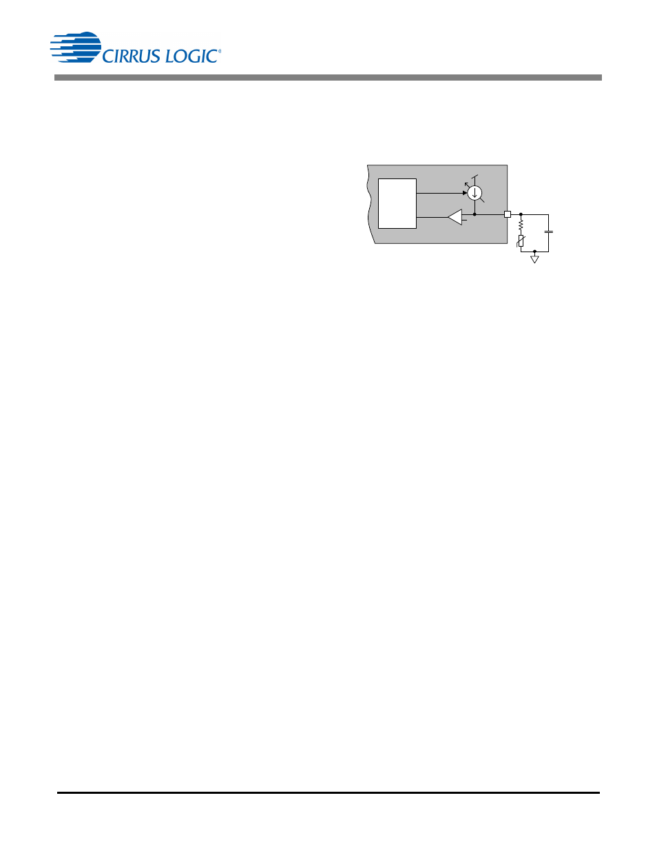
5.5.2 External Overtemperature Protection
The external overtemperature protection (eOTP) pin is
used to implement overtemperature protection. A negative
temperature coefficient (NTC) thermistor resistive network
is connected to pin eOTP, usually in the form of a series
combination of a resistor R
S
and a thermistor R
NTC
(see
Figure 14). The CS1680 cyclically samples the resistance
connected to pin eOTP.
The total resistance on the eOTP pin gives an indication of
the temperature and is used in a digital feedback loop to
adjust current I
CONNECT
into the NTC thermistor and
series resistor R
S
to maintain a constant reference voltage
V
CONNECT(th)
of 1.25V. Current I
CONNECT
is generated
from a controlled current source with a full-scale current of
80
A. When the loop is in equilibrium, the voltage on pin
eOTP fluctuates around voltage V
CONNECT(th)
. A
resistance ADC is used to generate I
CONNECT
. The ADC
output is filtered to suppress noise and compared against
a reference that corresponds to 125°C. A second low-pass
filter with a time constant of two seconds filters the ADC
output and is used to scale down the internal dim level of
the system (and hence LED current I
LED
) if the
temperature exceeds 95°C. The large time constant for
this filter ensures that the dim scaling does not happen
spontaneously and is not noticeable (suppress spurious
glitches). The eOTP tracking circuit is designed to function
accurately with external capacitance up to 470pF.
The tracking range of this resistance ADC is approximately
15.5k
to 4M. The series resistor R
S
is used to adjust
the resistance of the NTC thermistor to fall within the ADC
tracking range, allowing the entire dynamic range of the
ADC to be well used. The CS1680 recognizes a resistance
(R
S
+R
NTC
) equal to 20.3k
which corresponds to a
temperature of 95°C, as the beginning of an
overtemperature dimming event and starts reducing the
power dissipation. The output current is scaled until the
series resistance (R
S
+R
NTC
) value reaches 16.6k
(125°C). Beyond this temperature, the IC enters a fault
state and shuts down. This fault state is a latched
protection state, and the fault state is not cleared until the
power to the IC is recycled.
I
BUCKPK max
V
BUCKPK th
R
BUCK Sense
-------------------------------------
=
[Eq.7]
I
BUCKPK OCP
V
BUCKOCP th
R
BUCK Sense
-------------------------------------
=
[Eq.8]
CS1680
+
-
I
CONNE CT
V
CONNE CT
(th)
Comp_Out
eOTP
Control
eOTP
R
S
C
NTC
NTC
V
DD
2
(Optional )
Figure 14. eOTP Functional Diagram