Adjustment of zero point / span – WIKA S-10 User Manual
Page 8
1604457.14 GB/D/F/E 12/2009
14 WIKA Operating instructions/Betriebsanleitung/Mode d'emploi/Instrucciones de servicio S-10, S-11
1604457.14 GB/D/F/E 12/2009
15
WIKA Operating instructions/Betriebsanleitung/Mode d'emploi/Instrucciones de servicio S-10, S-11
Specifications
Oxygen version of model S-10
Pressure ranges
bar
As of 0 ... 0.1 / 50 INWC
Type of pressure
Gauge pressure
Materials
Wetted parts
316 Ti (up to 40 bar / 600 psi F 1058)
Internal transmission fluid
1)
Halocarbon oil
1)
Not for model with pressure ranges > 25 bar / 300 psi
Permissible temperature of
Medium
-20 ... +60 °C
-4 ... +140 °F
Functional test
Open pressure connections only after the system is without pressure!
Observe the ambient and working conditions outlined in section 7 „Technical
data".
Please make sure that the pressure transmitter is only used within the over-
load threshold limit at all times!
The output signal must be proportional to the pressure. If not, this might point to a
damage of the diaphragm. In that case refer to chapter 10 „Troubleshooting“.
When touching the pressure transmitter, keep in mind that the surfaces of
the instrument components might get hot during operation.
7. Starting, operation
GB
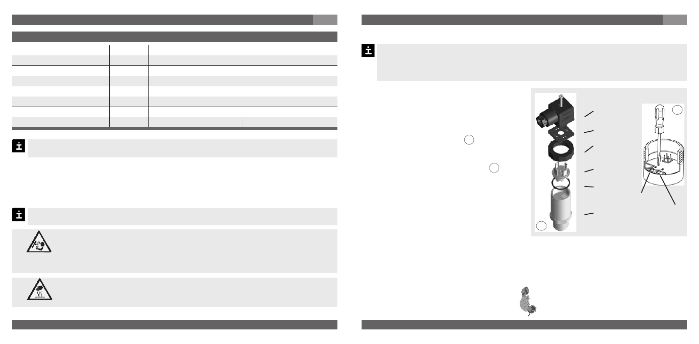
Z = Zero
S = Span
Female
connector
Sealing
Clamping
nut
Male
connector
Sealing
Case with
pressure
connection
Recommended recalibration cycle: yearly
For further information (+49) 9372/132-295
8. Adjustment of zero point / span
(only for pressure transmitter with clamping nut)
A
B
We do not recommend to adjust the span potentiometer. It is used for adjustment ex
factory and should not be adjusted by you unless you have adequate calibration equip-
ment at your disposal (at least three times more accurate than the instrument being
tested).
8. Adjustment of zero point / span
GB
Make sure wires are not cut or pinche
during disassembly and reassembly of
the connector.
Remove the female connector. Open
the pressure transmitter by detaching
the clamping nut (see Fig. A ). Carefully
remove the male connector from the
case.
Adjust the zero point (Z) (see Fig. B ) by
generating the lower limit of the pressure
range.
Adjust the span (S) by generating the
higher limit of the pressure range.
Check the zero point.
If the zero point is incorrect, repeat
procedure as required.
Reassemble the instrument carefully.
Make sure all sealings and o-rings are
not damaged and correctly installed to
assure the rated moisture ingress protec-
tion.
When designing your plant, take into account that the stated values (e.g.burst pressure,
over pressure safety) apply depending on the material, thread and sealing element used.
Warning
Caution