WIKA S-10 User Manual
Page 6
1604457.14 GB/D/F/E 12/2009
10 WIKA Operating instructions/Betriebsanleitung/Mode d'emploi/Instrucciones de servicio S-10, S-11
1604457.14 GB/D/F/E 12/2009
11
WIKA Operating instructions/Betriebsanleitung/Mode d'emploi/Instrucciones de servicio S-10, S-11
Specifications
Model S-10, S-11
Materials
Wetted parts
(Other materials see WIKA diaphragm seal program)
Pressure connection
»
316 Ti, S-11: O-ring: NBR
3)
{FPM/FKM}
Pressure sensor
»
316 Ti (as of 40 bar / 600 psi 13-8 PH)
Case
Stainless steel
Internal transmission fluid
4)
Synthetic oil
3)
O-ring made of FPM/FKM for model S-11
with integrated cooling element.
4)
Not for model S-10 with pressure ranges > 25 bar / 300 psi
Specifications
Model S-10, S-11
Pressure ranges
bar
0.1
0.16 0.25 0.4
0.6
1
1.6
2.5
4
6
10
16
Over pressure safety
bar
1
1.5
2
2
4
5
10
10
17
35
35
80
Burst pressure
bar
2
2
2.4
2.4
4.8
6
12
12
20.5 42
42
96
Pressure ranges
bar
25
40
60
100 160 250 400
600
1000
1)
Over pressure safety
bar
50
80
120 200 320 500 800
1200
1500
Burst pressure
bar
96
400
550 800 1000 1200 1700
2)
2400
2)
3000
Pressure ranges
psi
50 INWC
100 INWC 5
10
15
25
30
60
100
Over pressure safety
psi
14.5
29
29
58
72
145 145 240 500
Burst pressure
psi
29
35
35
69
87
170 170 290 600
Pressure ranges
psi
200
300
500 600 1000
1500
2000
Over pressure safety
psi
1160
1160
1160 1160 1740
2900
4600
Burst pressure
psi
1390
1390
5800 5800 7970
11,600
14,500
Pressure ranges
psi
3000
5000
8000
10,000
1)
15,000
1)
Over pressure safety
psi
7200
11,600
17,400
17,400
21,750
Burst pressure
psi
17,400
24,650
2)
34,800
2)
34,800
43,500
{Vacuum, gauge pressure, compound range, absolute pressure are available}.
1)
Only model S-10.
2)
For model S-11: The value specified in the table applies only when sealing is
realised with the sealing ring underneath the hex. Otherwise max. 1,500 bar /
21,000 psi applies.
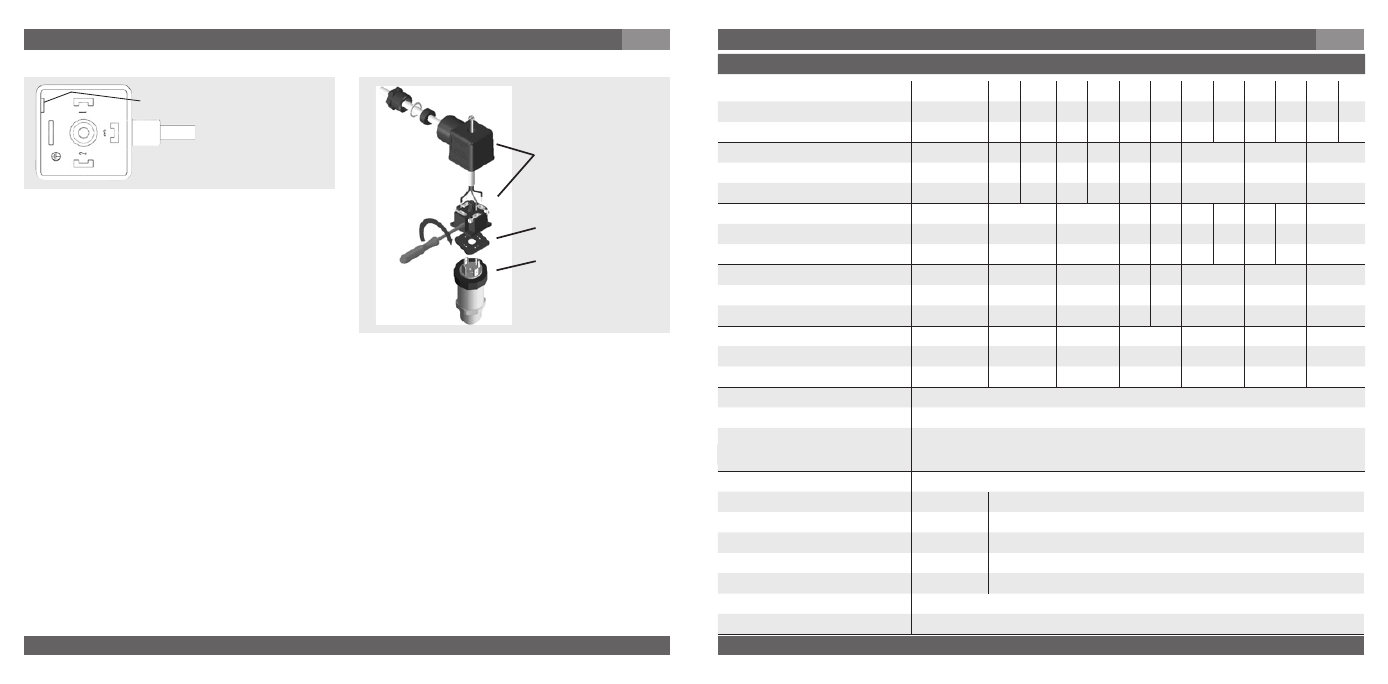
(D) Mounting hole
1. Loosen the screw (1).
2. Loosen the cable gland (2).
3. Pull the angle housing (5), with the
terminal block (6) inside, away from the
instrument.
4. Using the head of a small screwdriver in
the mounting hole (D), lever the terminal
block (6) out of the angle housing (5).
In order not to damage the sealing of the angle housing, do not try to push the terminal
block (6) out using the screw hole (1) or the cable gland (2).
5. Ensure that the conductor outer diameter you select is matched to the angle housing’s
cable gland. Slide the cable through the cable gland nut (2), washer (3), gland seal (4) and
angle housing (5).
6. Connect the flying leads to the screw terminals on the terminal block (6) in accordance
with the pin-assignment drawing.
7. Press the terminal block (6) back into the angle housing (5).
8. Tighten the cable gland (2) around the cable. Make sure that the sealing isn’t damaged
and that the cable gland and seals are assembled correctly in order to ensure ingress
protection.
9. Place the flat, square gasket over the connection pins on the top of the instrument
housing.
10. Slide the terminal block (6) onto the connection pins.
11. Secure the angle housing (5) and terminal block (6) to the instrument with the screw (1).
Assembly of L-connector DIN EN 17501-80 Form A
(6)
(5)
(1)
(2)
(3)
(4)
Clamping nut,
Male connector,
Case with
pressure connection
Sealing
Female
connector
7. Starting, operation
GB
7. Starting, operation
GB