DuraVent PelletVent Pro User Manual
Page 9
9
Figure 8
Pro pipe sections do not require any sealant;
however in certain instances high temp
silicone sealant may be used. Seal connection
where the inner liners overlap for best results
(Figure 5). Screws are not needed, but 1/4”
screws can be used if desired, however, be
sure you do not penetrate the inner liner.
E. When the pipe passes through the Ceiling
Support Firestop Spacer at ceiling, tighten
bolt and clamp around pipe. Where the vent
passes through additional floors and ceilings,
always install a Ceiling Support Firestop
Spacer.
F. ALWAYS MAINTAIN AT LEAST 1”
CLEARANCE FROM COMBUSTIBLE
MATERIALS TO THE VENT PIPE.
G. When the PelletVent Pro enters the attic,
install an Attic Insulation Shield around the
vent (Figure 6). This will prevent insulation
and debris from collecting near the vent
pipe. Use (4) nails or wood screws to secure
the base of the Attic Insulation Shield to the
framed opening. Adjust the height of the Attic
Insulation Shield by sliding the top cylindrical
shield over the one from the base. Ensure
that the top of the Shield is above the level
of building insulation. Secure the Shield in
place with at least two (2) sheet metal screws
through the side of the cylindrical shield.
Attach collar around pipe, then lower to the top
of the Attic Insulation shield.
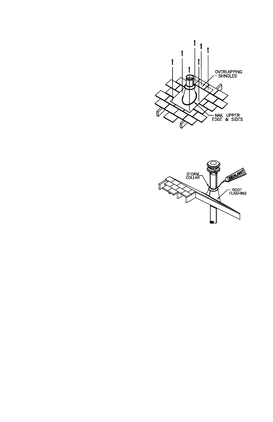
H. After lining up for the hole in roof, using
the same method as 2. (B), cut either a round
or square hole in the roof (Figure 7). Always
cut the hole with the proper clearance to the
vent pipe. Install the upper edge and sides
of Flashing under the roofing materials and
nail to the roof along the upper edge and
sides (Figure 8). Do not nail across the lower
edge. Seal all nail heads with non-hardening
waterproof sealant.
I. To finish, apply non-hardening waterproof
sealant where the Storm Collar will meet the
vent and Flashing; slide Storm Collar down
until it rests upon the Roof Flashing (Figure 9).
Holding the base of Cap, firmly twist lock your
Vertical Termination Cap onto, supported Pipe
Section protruding through the roof line.
Figure 9