Kramer Electronics 704 User Manual
Page 12
KRAMER ELECTRONICS LTD.
9
6.6 Getting to Know the TP-12N Video/Audio Twisted-Pair Line Receiver
The KRAMER
TP-12N Video/Audio Line Receiver works in conjunction with the TP-11N Video/Audio Line
Transmitter. The
TP-12N allows parallel connection of several units on the same line (one transmitter/multiple
receivers), that can be tapped at any point without affecting image quality. When connecting several units, all
the termination switches on the rear panel of the
TP-12N machines, except for the last on the line, should be
toggled to the Hi-Z position. The frequency response of the
TP-12N matches that of the TP-11N transmitter,
and it provides polarity switching on the rear panel.
NOTE
For Installation, operation, maintenance and troubleshooting instructions please refer to sections 8-13.
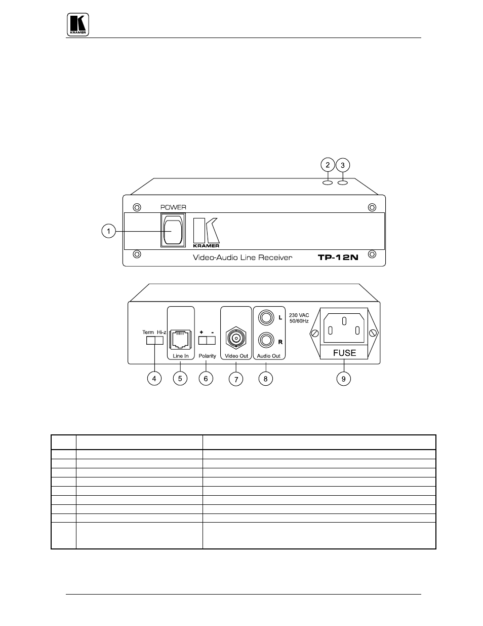
Figure : TP-12N Front/Rear Panel Features
Table 5: TP-12N Front/Rear Panel Features
No.
Feature
Function
1. Illuminated power switch
Supplies power to the unit.
2.
GAIN trimmer
Controls video level of output (accessible from bottom).
3.
HF trimmer
Controls cable equalization of the video output (accessible from bottom).
4.
Term/Hi-Z switch
Selects "
Term" or "Hi-Z" impedance (for looping select "Hi-Z").
5.
LINE in telephone socket
Balanced input.
6.
Polarity switch
Inverts the incoming balanced signal.
7. BNC
Video out connector
Amplified and buffered video output.
8. RCA
Audio out connectors
Amplified and buffered audio
output.
9. Power Connector
A 3-prong AC connector allows power to be supplied to the unit.
Directly underneath this connector, a fuse holder houses the appropriate
fuse.