Figure 6: fc-24eth ethernet controller rear panel – Kramer Electronics FC-24ETH User Manual
Page 15
Defining the FC-21ETH, FC-22ETH and
FC-24ETH Ethernet Controllers
11
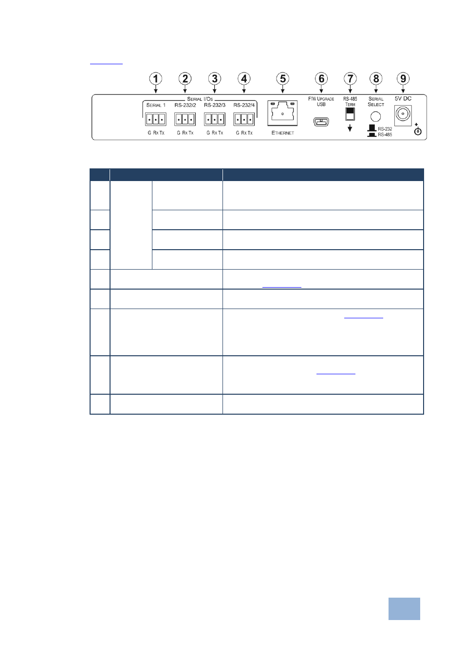
defines the rear panel of the FC-24ETH.
Figure 6: FC-24ETH Ethernet Controller Rear Panel
#
Feature
Function
1
SERIAL
I/Os
SERIAL 3-pin
Terminal Block
Connect to an RS-232 or RS-485 controlled device.
When connecting as an RS-485 port, the connections
are G, B, A in place of G, Rx, Tx
2
RS-232/2 3-pin
Terminal Block
Connect to an RS-232 controlled device
3
RS-232/2 3-pin
Terminal Block
Connect to an RS-232 controlled device
4
RS-232/2 3-pin
Terminal Block
Connect to an RS-232 controlled device
5
ETHERNET RJ-45
Connector
Connect to the PC or other controller directly or via a
LAN (see
Section
6
F/W UPGRADE USB
Connector
Connect to a PC to upgrade the firmware
7
RS-485 TERM Switch
Terminates the RS-485 bus, (see
Section
Slide down when this is the last device on an RS-485
bus.
Slide up when this device is not the last device on an
RS-485 bus
8
SERIAL SELECT Button
Selects either RS-232 or RS-485 serial communication
for the SERIAL port, (see
Section
).
Depress for RS-485 serial communication.
Release for RS-232 serial communication
9
5V DC Connector
Connect to the 5V DC power supply, center pin
positive