2 defining the fc-22eth ethernet controller, Defining the fc-22eth ethernet controller, Figure 3: fc-22eth ethernet controller front panel – Kramer Electronics FC-24ETH User Manual
Page 12
8
Defining the FC-21ETH, FC-22ETH and
FC-24ETH Ethernet Controllers
4.2
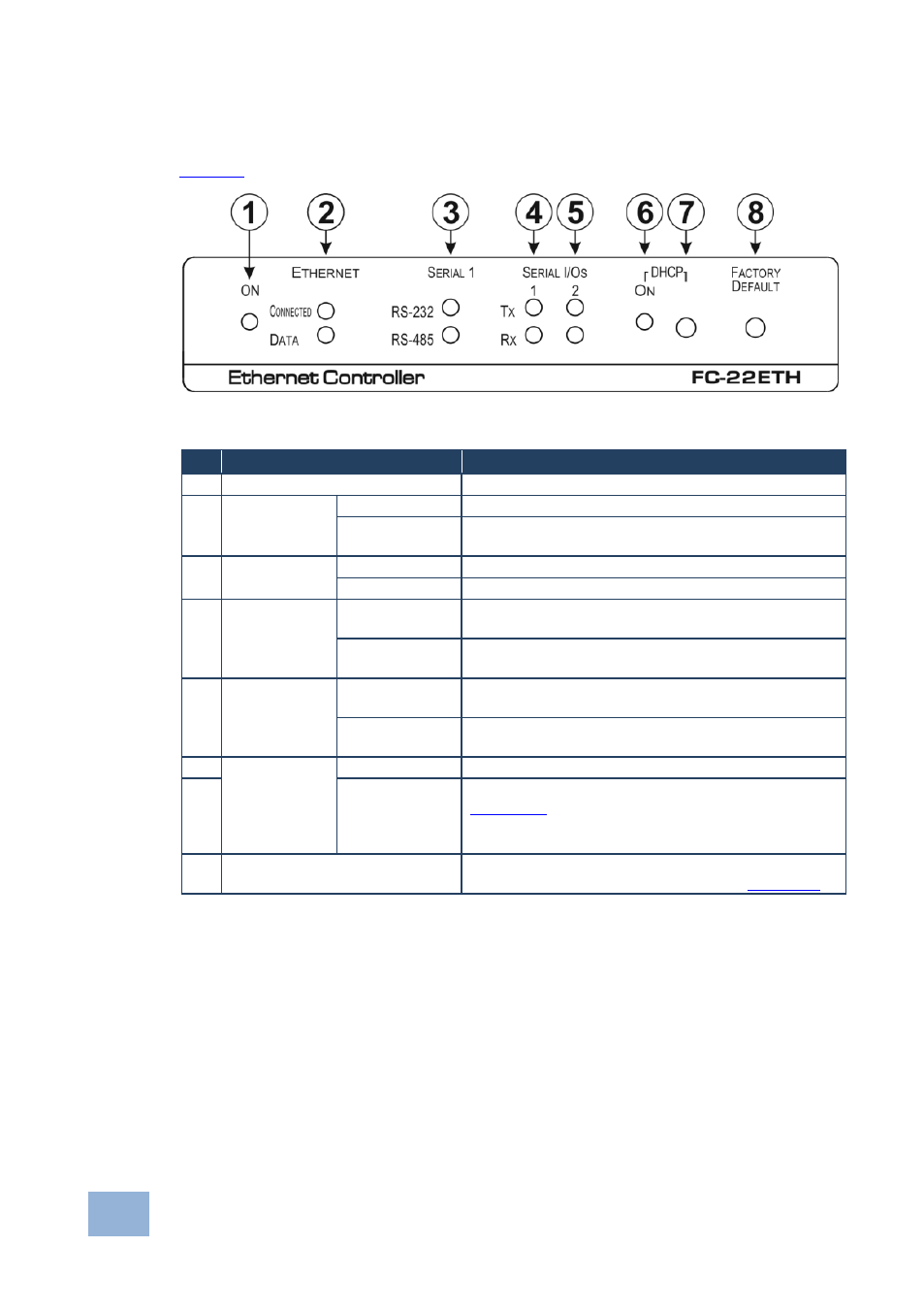
Defining the FC-22ETH Ethernet Controller
defines the front panel of the FC-22ETH.
Figure 3: FC-22ETH Ethernet Controller Front Panel
#
Feature
Function
1
ON LED
Lights green when the unit is on
2
ETHERNET
LEDs
CONNECTED
Lights yellow when the Ethernet port is connected
DATA
Flashes green when data is transferred over the
Ethernet link
3
SERIAL 1
LEDs
RS-232
Lights green when RS-232 is selected
RS-485
Lights green when RS-485 is selected
4
SERIAL I/Os
1 LEDs
Tx
Flashes red when the device is transmitting data over
serial port 1
Rx
Flashes green when the device is receiving data on
serial port 1
5
SERIAL I/Os
2 LEDs
Tx
Flashes red when the device is transmitting data over
serial port 2
Rx
Flashes green when the device is receiving data on
serial port 2
6
DHCP
ON LED
Lights green when DHCP is selected
7
Button
Selects either DHCP or static IP addressing, (see
Section
).
Press to toggle the selection between DHCP and
static IP addressing
8
FACTORY DEFAULT Button
Press and hold while power-cycling the device to
reset to factory default parameters, (see
Section