3 defining the fc-24eth ethernet controller, Defining the fc-24eth ethernet controller, Figure 5: fc-24eth ethernet controller front panel – Kramer Electronics FC-24ETH User Manual
Page 14
10
Defining the FC-21ETH, FC-22ETH and
FC-24ETH Ethernet Controllers
4.3
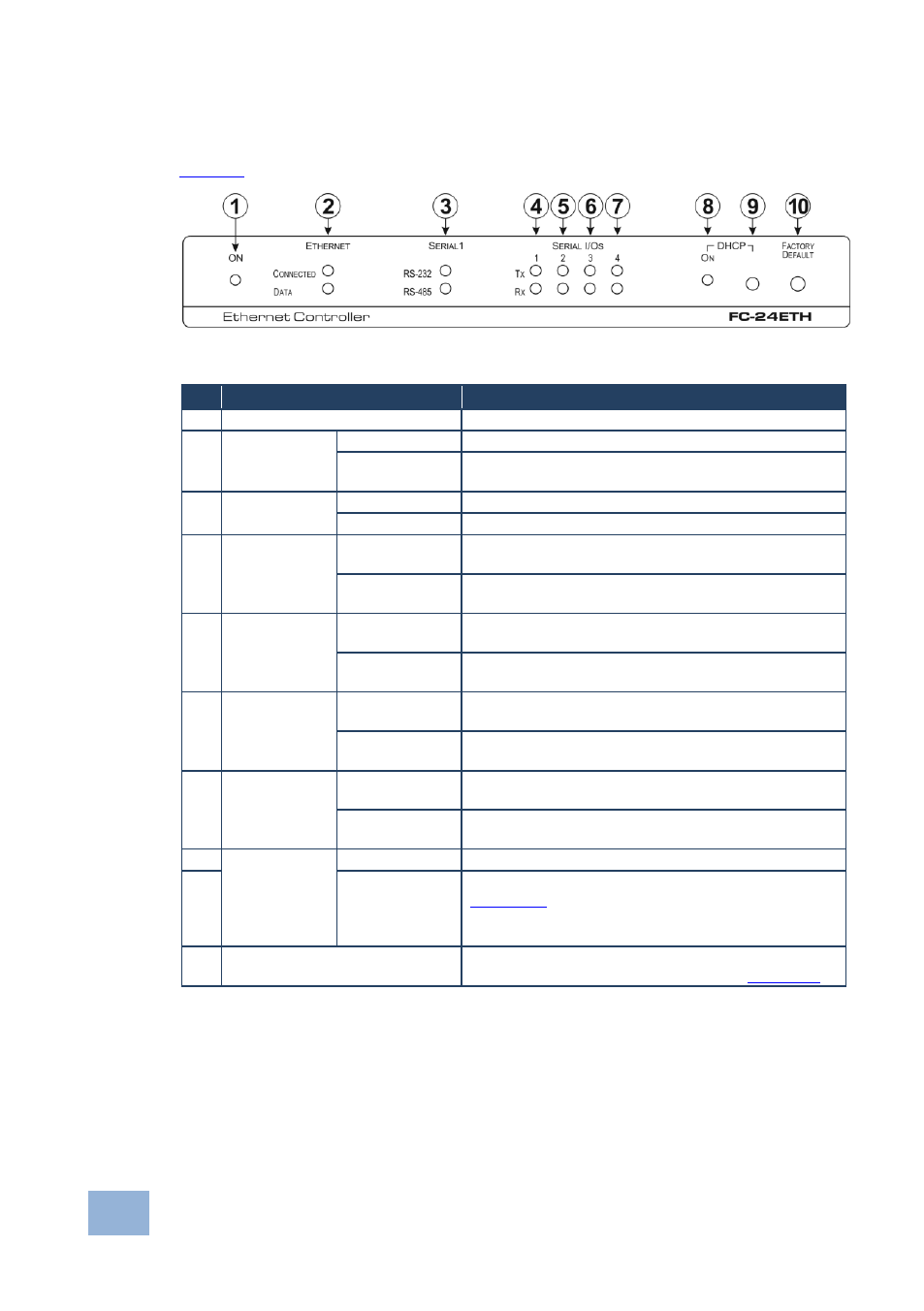
Defining the FC-24ETH Ethernet Controller
defines the front panel of the FC-24ETH.
Figure 5: FC-24ETH Ethernet Controller Front Panel
#
Feature
Function
1
ON LED
Lights green when the unit is on
2
ETHERNET
LEDs
CONNECTED
Lights yellow when the Ethernet port is connected
DATA
Flashes green when data is transferred over the
Ethernet link
3
SERIAL 1
LEDs
RS-232
Lights green when RS-232 is selected
RS-485
Lights green when RS-485 is selected
4
SERIAL I/Os
1 LEDs
Tx
Flashes red when the device is transmitting data over
serial port 1
Rx
Flashes green when the device is receiving data on
serial port 1
5
SERIAL I/Os
2 LEDs
Tx
Flashes red when the device is transmitting data over
serial port 2
Rx
Flashes green when the device is receiving data on
serial port 2
6
SERIAL I/Os
3 LEDs
Tx
Flashes red when the device is transmitting data over
serial port 3
Rx
Flashes green when the device is receiving data on
serial port 3
7
SERIAL I/Os
4 LEDs
Tx
Flashes red when the device is transmitting data over
serial port 4
Rx
Flashes green when the device is receiving data on
serial port 4
8
DHCP
ON LED
Lights green when DHCP is selected
9
Button
Selects either DHCP or static IP addressing, (see
Section
).
Press to toggle the selection between DHCP and
static IP addressing
10
FACTORY DEFAULT Button
Press and hold while power-cycling the device to
reset to factory default parameters, (see
Section