E lectron ics, Matrix routing switcher – Kramer Electronics TailorMade User Manual
Page 8
8
K R A M E R
E lectron ics
MATRIX ROUTING SWITCHER
2.4 COMMUNICATION PROTOCOL 2000 TM
INCLUDING OPTIONS (02/09/2005 VER-5.06)
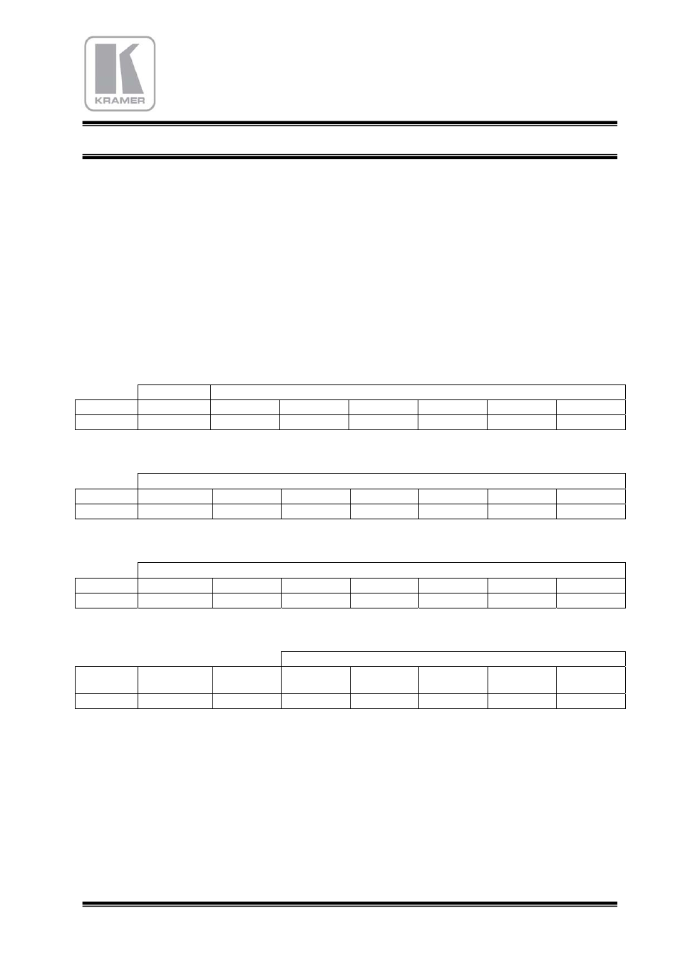
This RS-232 / RS-485 communication protocol uses four bytes of information as defined
below.
For RS-232, a null-modem connection between the machine and controller is used. The
default data rate is 9600 baud, with no parity, 8 data bits and 1 stop bit.
MSB
LSB
1
st
byte
DEST
INSTRUCTION
0 D N5 N4 N3 N2 N1 N0
7 6 5 4 3 2 1 0
2
nd
byte INPUT / DATA_1
1 D6 D5 D4 D3 D2 D1 D0
7 6 5 4 3 2 1 0
3
rd
byte
OUTPUT / ADRESS / DATA_2
1 A6 A5 A4 A3 A2 A1 A0
7 6 5 4 3 2 1 0
4
th
byte
LAYER NUMBER
1
Bit 7
output
Bit 7
input
L4 /
Bit 8 output
L3 /
Bit 8 input
L2 L1 L0
7 6 5 4 3 2 1 0
1
st
BYTE:
Bit 7 – Defined as 0.
D – “DEST”: 0 - for sending to the switcher (from the PC or keyboard).
1 - for sending to the PC or keyboard (from the switcher).
N5…N0 – “INSTRUCTION”
The function that is to be performed by the switcher(s) is defined by the INSTRUCTION (6
bits). The instruction codes are defined according to the table below (INSTRUCTION NO. is
the value to be set for N5…N0).