E lectron ics, Matrix routing switcher – Kramer Electronics TailorMade User Manual
Page 19
19
K R A M E R
E lectron ics
MATRIX ROUTING SWITCHER
Source
Object connected on an input of the switcher.
Disconnect
A destination is disconnected when there is no link
with any source. This status is symbolized by a
fictive object that has to be assigned as a source
called « disconnected ».
7.3 STARTING
7.3.1 Power On
The software MatrixOp4 should be installed on
hard disk.
Switch Power on of the routing switcher, the PC
and the screen.
Start the system by clicking « matrixop4.exe », then
the switching program takes over and runs
automatically.
After an auto-test, the program is ready, and
positions itself on the page that has been previously
automatically protected.
It establishes the links, and transmits them to the
matrix.
The auto-test was designed to check the correct
functioning of the matrix.
7.3.1.1 SET-UP
When just installed, the software may be initialized.
The matrix may be linked. Setup request
automatically the size of the matrix.
If fault arises :
1) Check that the routing switcher is « power on »
2) Select another port
3) Check the link between PC and Matrix unit
with the RS-232 cable
4) The LED display of the routing switcher must
lit a switching to every transmission.
5) Check if there is evidence of connection
between the devices declared in the menus and
the real configurations of the matrix. Check
that there is not more numbers than the
physical capacity of the matrix.
Verify the whole matrix/PC and restart the
program.
7.3.2 STOPPING THE SYSTEM
Turn off of the power.
The switching off of power to the central unit (PC)
and its screen doesn’t alter the connection of the
matrix (as long as the matrix is powered).
Switching off power to the routing switcher will
cease all switching actions. When switching on the
matrix, it will keep its previous configuration.
MatrixOp4 can reset the matrix however with the
“initialization” command.
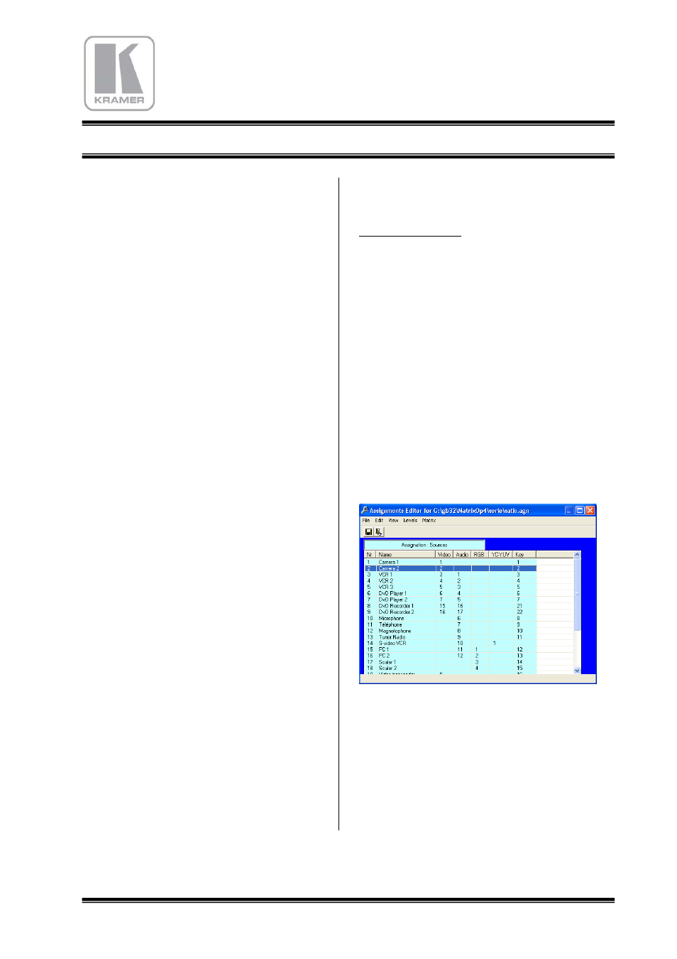
7.4 ASSIGNMENTS EDITOR
7.4.1 COMMAND : Assignments
To run this subroutine, click the assignment
command. This program establishes the name and
the state of the peripheral objects.
This is the only moment where the numbering of
the audio and video connectors is shown.
When opening of this program, this window
appears, as well as a schematic representation of
the routing switcher and of the peripheral objects.
This very simplified schematic is as a real wiring
map sheet.
Four layers can work simultaneously, and each one
can have a different size.
This list form can be managed with all the function
menu, as file/edit/view/audio levels/ matrix upload.