E lectron ics, Matrix routing switcher – Kramer Electronics TailorMade User Manual
Page 4
4
K R A M E R
E lectron ics
MATRIX ROUTING SWITCHER
The cards are horizontally located, and can be
extracted by the front panel. Each card own up to
32 stereo plugs. There is two types of audio cards :
-
Input audio cards.
Called WMI, these cards are identical between
themselves. The only differences are the serigraphy
of the panel and its position in the slots.
When viewing from the rear panel, these cards are
immediately slotted near the QMOSD card
(communication card). Their 32 audio plugs can be
set up in factory, as balanced or unbalanced, or
mixed.
Balanced mode has a +4dB level under 6 KOhms
impedance., and the unbalanced mode, -6dB under
10 KOhms. Dynamic is 12 dB. The inputs are
directly introduced into the integrated circuits, and
have no galvanic isolation.
-
Output audio cards.
Called WMO, these cards are physically identical
between themselves, but have to be programmed
for identification. Their position is immediately
near the input cards. Their 32 audio plugs have no
galvanic isolation. The output impedance is 50
Ohms. We can use the output in balanced mode, as
in unbalanced only without connecting the inverted
pin. (Do not connect this pin to the ground).
Up to 32 VCA (Voltage Control Amplifiers) can be
wired in factory. So the audio level can be adjusted
with a special RS 232 command.
1.7 OTHERS SECTIONS
YC (S-video), component YUV, and RGsB can be
realized with the analogue video cards, with the
same principle as RGBhv section.
1.8 COMMUNICATION
The card called QMOSD is the heart of the
KRAMER matrix routing switcher. This card own
a clock generator, a microcontroller, and provides
the service signal to the others cards of the
machine. The reception and the treatment of the
RS232, RS422 and Ethernet is made inside and the
datas are then transferred the concerned switchers.
As there is no keyboard on the front panel of the
matrix, the QMOSD card take on the dialog with
the external keyboard by the RS422 link.
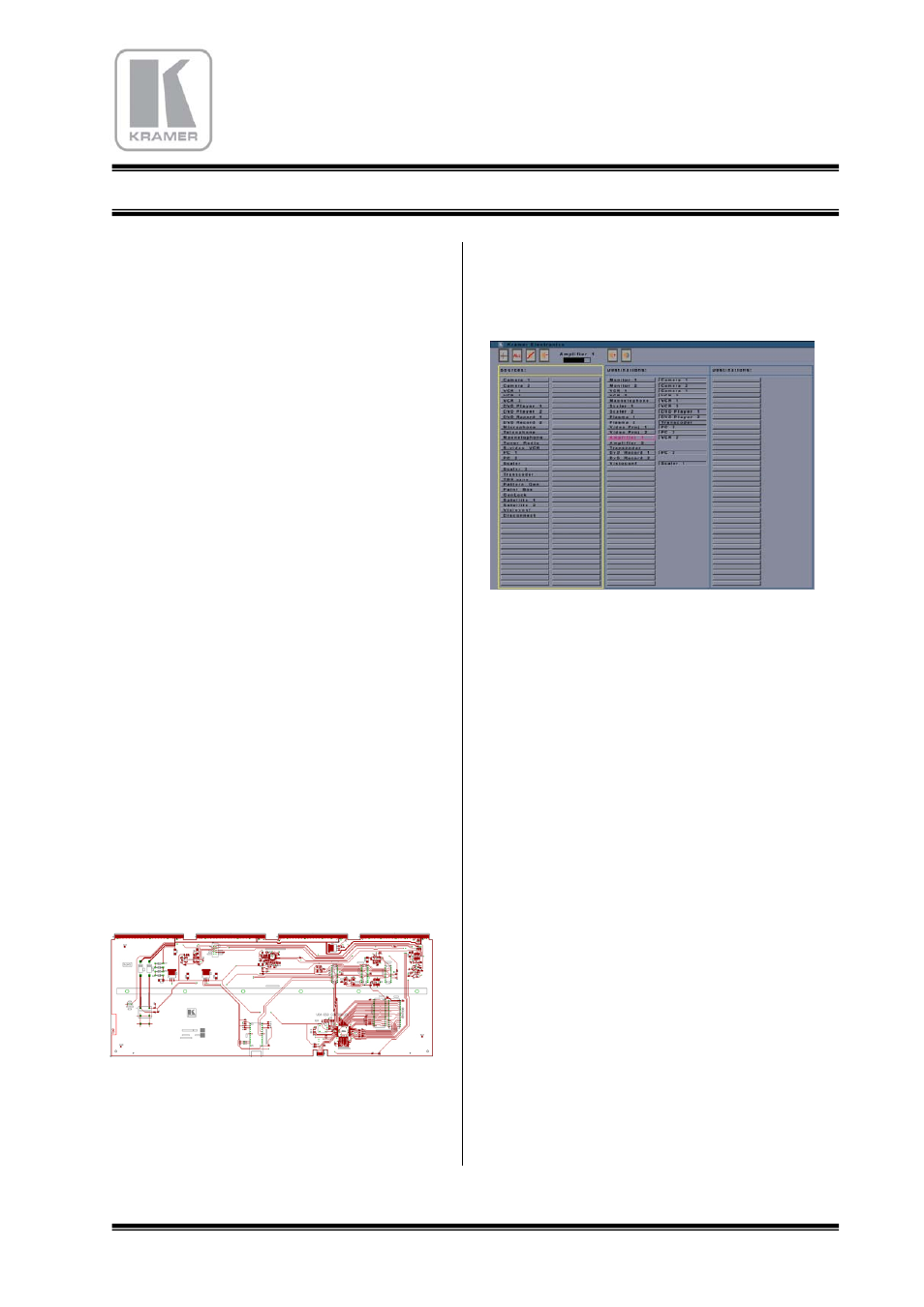
1.9 ON SCREEN DISPLAY
The GMOSD card has a SVGA 800x600 generator
that is available on a SubD-HD15 connector. An
external screen can be connected on, and propose a
listing of the matrix status.
On the left is shown the list of 80 input sources, as
13 characters names.
On the right area are shown 80 outputs name, with
the status of switch.
A mouse can be connected on a USB-A connector,
to control the upper tool bar, and to create switches.
The loading of this table is automatically done with
the MatrixOp4 software, after entering the
assignment operation.
1.10 INTERVAL SWITCHING
Switching during the black interval is basic to get a
clean change of picture, without break of the
synchronization, and cut in the middle of the
screens. When the reference signal is present
(blackburst), the switching takes place in the
beginning of the video frame, that is to say in the
middle of the line N°2 or 314 in PAL/SECAM
(N°2 or 264 in NTSC). The maximum waiting time
is of 20 mS in PAL and 16,7 mS in NTSC. This
operation can be effective only when the sources
are synchronized with the blackburst. If this
condition is not perform, then the switch is made
normally out of the interval time.