6 wiring the twisted pair rj-45 connectors, Wiring the twisted pair rj-45 connectors, Figure 7: tp pinout wiring – Kramer Electronics VM-114H2C User Manual
Page 18: 6wiring the twisted pair rj-45 connectors
VM-114H2C - Wiring the Twisted Pair RJ-45 Connectors
15
6
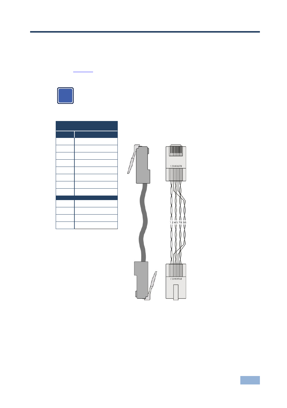
Wiring the Twisted Pair RJ-45 Connectors
When using STP cable, connect/solder the cable shield to the RJ-45 connector
shield.
defines the TP pinout using a straight pin-to-pin cable with RJ-45
connectors.
Note, you must connect/solder the cable ground shielding to the
connector shield.
EIA /TIA 568B
Figure 7: TP Pinout
Wiring
PIN
Wire Color
1
Orange / White
2
Orange
3
Green / White
4
Blue
5
Blue / White
6
Green
7
Brown / White
8
Brown
Pair 1
4 and 5
Pair 2
1 and 2
Pair 3
3 and 6
Pair 4
7 and 8
i
See also other documents in the category Kramer Electronics Accessories for electrical:
- VM-114H (22 pages)
- VM-114H4C (23 pages)
- VS-81ETH (27 pages)
- VS-81ETH (41 pages)
- VM-9T (13 pages)
- VP-12NHD (15 pages)
- VP-5R (20 pages)
- VP-6A (15 pages)
- PT-5R/T (13 pages)
- TP-102HD (13 pages)
- TP-104HD (33 pages)
- TP-112HD (13 pages)
- TP-114 (13 pages)
- TP-202 (15 pages)
- TP-205A (15 pages)
- TP-210 (14 pages)
- TP-210A (15 pages)
- tp-219hd (16 pages)
- TP-305A (15 pages)
- TP-310A (18 pages)
- TP-410 (34 pages)
- VM-1H4C (17 pages)
- VP-200xlT (31 pages)
- VP-300THD (12 pages)
- VPM-2 (42 pages)
- SI-1VGA (2 pages)
- SID-DP (2 pages)
- SID-DVI (2 pages)
- SID-H (2 pages)
- SID-VGA (2 pages)
- SID-X1 (2 pages)
- SID-X1 (23 pages)
- SID-X1N (23 pages)
- SID-X2N (31 pages)
- SID-X3N (22 pages)
- 622R (17 pages)
- VS-169TP (7 pages)
- VS-169TP (45 pages)
- WSI-1VGA (2 pages)
- TP-107AV (32 pages)
- RC-62 (94 pages)
- RC-5B2 (137 pages)
- WP-500 (2 pages)
- SV-552 (22 pages)