4 ir local control and pass-through example 2 – Kramer Electronics VM-114H2C User Manual
Page 16
VM-114H2C - Operating the VM-114H2C
13
5.3.4
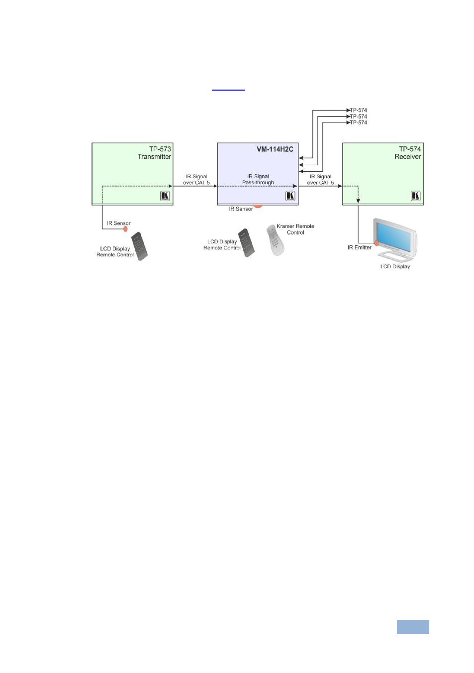
IR Local Control and Pass-Through Example 2
The configuration is shown in
Figure 5: VM-114H2C IR Control and Pass-Through Example 2
An IR sensor is connected to the TP-573 transmitter.
An LCD display is connected to the TP-574 receiver via an IR emitter.
Both the TP-573 and the TP-574 are connected to the VM-114H2C via TP
cabling.
Point the LCD display remote control either at the TP-573 IR sensor or at the
VM-114H2C IR sensor to control the LCD display. Point the Kramer remote control
at the VM-114H2C IR sensor to control the VM-114H2C.
See also other documents in the category Kramer Electronics Accessories for electrical:
- VM-114H (22 pages)
- VM-114H4C (23 pages)
- VS-81ETH (27 pages)
- VS-81ETH (41 pages)
- VM-9T (13 pages)
- VP-12NHD (15 pages)
- VP-5R (20 pages)
- VP-6A (15 pages)
- PT-5R/T (13 pages)
- TP-102HD (13 pages)
- TP-104HD (33 pages)
- TP-112HD (13 pages)
- TP-114 (13 pages)
- TP-202 (15 pages)
- TP-205A (15 pages)
- TP-210 (14 pages)
- TP-210A (15 pages)
- tp-219hd (16 pages)
- TP-305A (15 pages)
- TP-310A (18 pages)
- TP-410 (34 pages)
- VM-1H4C (17 pages)
- VP-200xlT (31 pages)
- VP-300THD (12 pages)
- VPM-2 (42 pages)
- SI-1VGA (2 pages)
- SID-DP (2 pages)
- SID-DVI (2 pages)
- SID-H (2 pages)
- SID-VGA (2 pages)
- SID-X1 (2 pages)
- SID-X1 (23 pages)
- SID-X1N (23 pages)
- SID-X2N (31 pages)
- SID-X3N (22 pages)
- 622R (17 pages)
- VS-169TP (7 pages)
- VS-169TP (45 pages)
- WSI-1VGA (2 pages)
- TP-107AV (32 pages)
- WP-500 (2 pages)
- SV-552 (22 pages)
- WP-501 (16 pages)
- RC-62 (94 pages)