Installation procedure – Muxlab Component Video Hub User Manual
Page 9
© MuxLab Inc.
Component Video Hub Installation Guide
Page 9
Figure 6: 16-port rack-mount installation
3.5.
Installation Procedure
The Component Video Hub is available in 8-port (500250, 500251) and
16-port (500252, 500253) versions. In order to install the product, please
follow the steps below:
1. Install the Component Video Hub in its final location by performing steps 1
or 2 listed in the previous section.
2. Ensure that the power is turned off on the component video source and
displays.
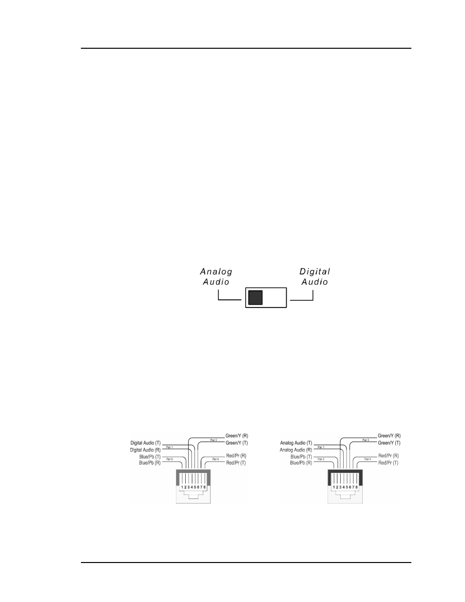
3. If audio will be transmitted along with video, set the hub to digital or
analog audio by sliding the switch on the rear panel to the appropriate
position as shown in the diagram below. The factory default setting is
“analog audio”.
4. In order to distribute component video (YPbPr/RGB) and audio (optional),
one (1) Component Video Balun must be connected at the component
video source and at each component video display. To install the baluns,
perform the following steps (5, 6 and 7):
5. Identify the pin configuration of the baluns. Three (3) twisted pairs are
required for video and one (1) twisted pair is required for optional digital
audio. The pin configuration follows the EIA/TIA 568A/B standard. The
Component Video Baluns are reverse polarity sensitive. Please ensure that
wiring is straight-through (Ring to Ring, Tip to Tip).
6. Plug one (1) Component Video/Digital Audio Balun (500050, 500051) or
Component Video/Analog Audio Balun (500052, 500053) into the