Troubleshooting, Application tips – Muxlab VGA Balun Kit User Manual
Page 2
© MuxLab Inc.
3.
Turn off power and disconnect the PC and VGA display equipment by following the
manufacturer’s instructions.
4.
Make certain that modular outlets and cross connects to which you will connect the VGA
Balun are configured properly and labeled appropriately to identify the circuit.
5.
Caution: Do not connect the VGA Balun to a telecommunication outlet wired to unrelated
equipment. Making such a connection may damage the equipment and/or the balun. Please
ensure that all wiring is “straight-through” twisted pair.
6.
Verify that the desired twisted pairs are not being used for other LAN or telephone equipment.
7.
The VGA Baluns operate in pairs.
8.
Connect the 500010 to the VGA port of the PC or VGA splitter/booster. Tighten the mounting
screws on each balun.
9.
Caution: Do not mount the balun over equipment ventilation openings. Covering the openings
may cause the equipment to overheat.
10. Connect a 4-pair Cat 5 cable from the RJ45 8-position modular jack of the VGA Balun to the
twisted pair cabling of the building.
11. Connect a 500011 or 500014 to the VGA display screen.
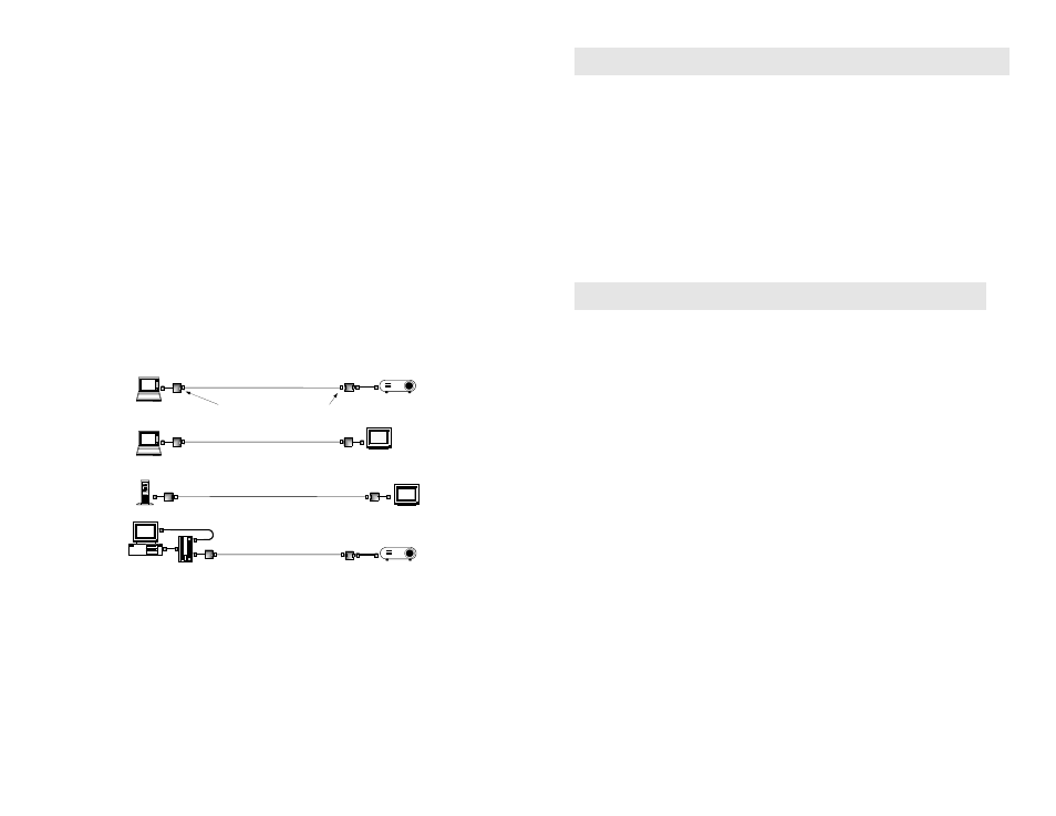
12. Connect a 4-pair Cat 5 cable from the RJ45 connector of the VGA Balun to the appropriate
modular wall outlet. See typical application below.
13. Power on the PC and VGA monitor.
14. Set monitor Contrast and Brightness to the desired levels.
PC and keyboard
CRT Monitor
500011
Laptop computer
500014
Laptop computer
Multimedia
Projector
500011
500010
Category 5
4-Pair
Shielded Twisted Pair
Flat-screen LCD Monitor
Shielded RJ45
connector
Shielded RJ45
connector
Multimedia
Projector
VGA balun
Instructor's PC
1x2 VGA
Splitter/Amplifier
VGA cable
Troubleshooting
If your equipment malfunctions with VGA Baluns in place, follow the troubleshooting
procedures below:
1.
Perform diagnostics on your video equipment by following the manufacturer’s
instructions.
2.
Check all the connections and verify the pin configuration.
3.
The maximum distances supported by the VGA Balun are dependent on the type of UTP
cable and image resolution of the PC’s VGA interface. Ensure that the maximum
recommended operational distances have not been exceeded.
4.
Check that only twisted pair patch cords are being used.
5.
Replace the VGA Balun with another balun that is known to be working.
6.
If you still cannot diagnose the problem, call MuxLab for support at 1-877-689-5228 or
514-905-0588.
Application Tips
1.
For proper operation, the VGA source and VGA display must share a common ground.
When the signal ground between the VGA source and VGA display is not common, then
Category 5 shielded twisted pair cable and shielded RJ45 connectors must be used. For more
information, please consult MuxLab’s VGA Balun Application Guide available on-line at
www.muxlab.com.
2.
The VGA Balun does not support the VGA handshaking and control signals as required by
certain video monitors. Before installing the VGA Baluns, connect the standard VGA cable
between the VGA source and destination and set the monitor to the desired attributes. Then
install the VGA Baluns and the twisted pair cable.
3.
For optimum results and maximum distance performance, first set the brightness and contrast
levels on the monitor to the maximum settings. Then install the VGA Baluns and the monitor
in its final location. After the monitor is installed in its final location, adjust the brightness and
contrast to the desired levels.
4.
If the video image is not present or is poorly synchronized, there may be a grounding
problem or a high level of noise on the line. To correct the problem, verify ground
continuity on the transmitting and receiving ends of the units or use shielded twisted pair
(STP) cable between the VGA Baluns.
5.
In certain PC applications such as Microsoft PowerPoint presentations, image resolution
may be less critical and therefore longer than specified distances may be achieved.