Shaft sleeve (126) installation, Impeller (101) installation, Warning – Goulds Pumps 3100 - IOM User Manual
Page 41: Casing (100) installation
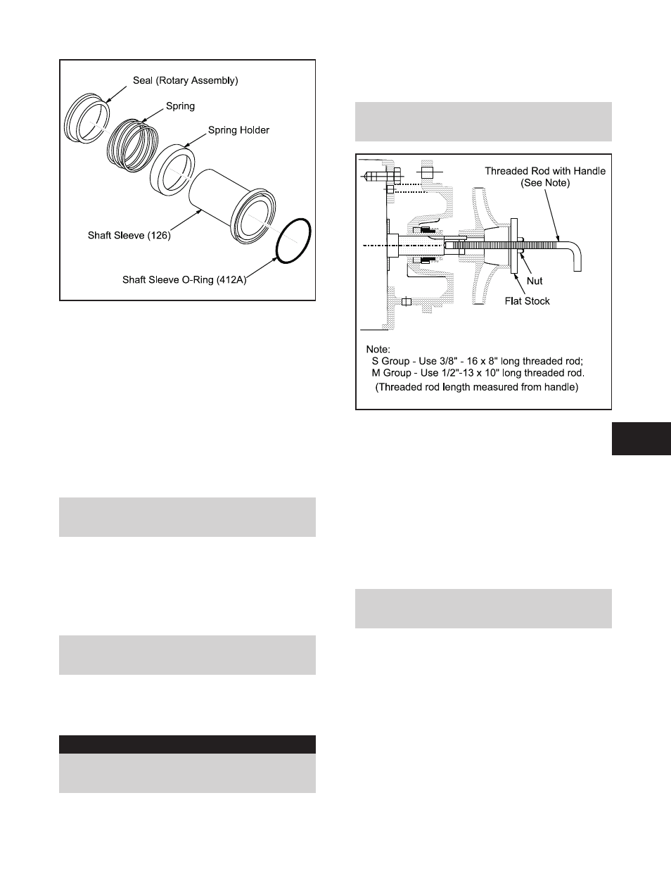
14. Install spring over shaft sleeve (126) against
spring holder.
15. Install seal (rotary assembly) onto shaft sleeve
(126) until face of seal is flush to open end of
sleeve.
SHAFT SLEEVE (126) INSTALLATION
16. Lubricate sleeve O-ring (412A) with the same
lubricant used for mechanical seal parts
(Table 6).
17. Install O-ring (412A) into O-ring groove on shaft
sleeve (126).
NOTE: Anti-galling compound can be applied
to shaft sleeve bore to aid in future
disassembly.
18. Install shaft sleeve (126) on motor shaft with
mechanical seal face towards the motor.
IMPELLER (101) INSTALLATION
19. Place impeller key (178) in keyway on motor
shaft.
NOTE: Impeller Key (178) will extend beyond
end of motor shaft at this point in the
reassembly procedure.
20. Apply anti-galling compound to motor shaft
outside diameter to aid in assembly and future
disassembly.
▲
!
WARNING
Wear heavy work gloves when handling
impeller (101) as sharp edges may cause
physical injury.
21. Align keyway in impeller (101) with impeller key
(178) on motor shaft. Install impeller (101) onto
shaft far enough to engage impeller nut (304).
NOTE: Do not force impeller onto shaft. If fit
is tight between motor shaft and impeller bore,
use puller (Fig. 30).
22. Lubricate impeller nut O-ring (412A) with the
same lubricant used for mechanical seal parts
(Table 6).
23. Install O-ring (412A) into O-ring groove on
impeller nut (304).
24. Thread impeller nut (304) into motor shaft.
Tighten impeller nut (304)
CASING (100) INSTALLATION
25. Install casing O-ring (412K) into casing (100).
NOTE: Anti-galling compound can be applied
to outside diameter of the seal chamber (184)
to aid in future disassembly.
26. Install casing:
M-Group - use hex cap screws (370).
S-Group - use hex cap screws (370) on 8-inch
pump, or hex nuts (425) and studs (356A) on
6-inch pump.
27. Tighten bolts in a criss-cross pattern to values
indicated in Table 7.
3100 IOM 1/97
33
6
Fig. 29
Fig. 30