Goulds Pumps 3100 - IOM User Manual
Page 34
MAINTENANCE ON MECHANICAL SEAL
4.
Place sling from hoist through webbing of motor
adapter (504) or seal chamber/adapter (184).
5.
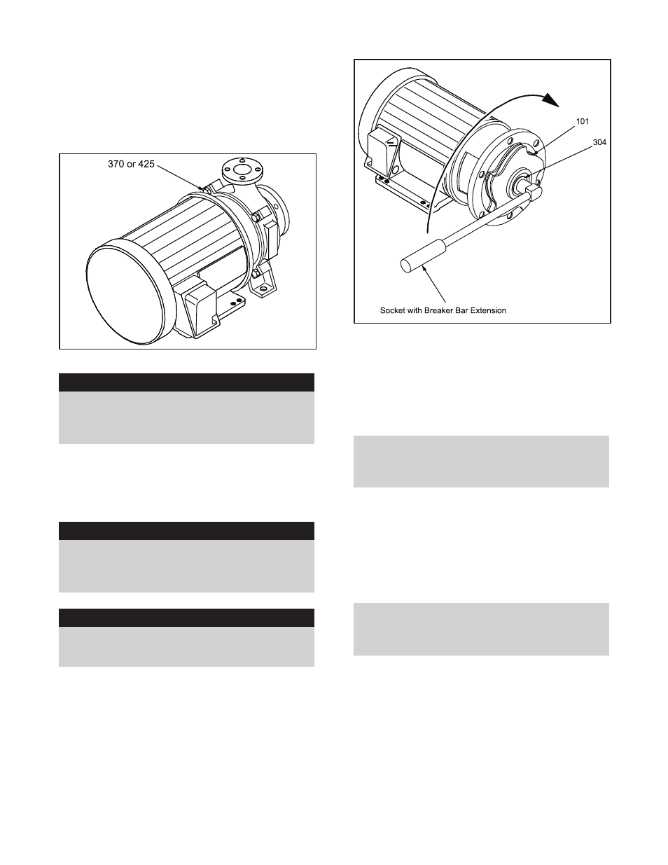
Remove casing bolts (370) or casing nuts (425),
then slide back pull-out assembly away from
casing (Fig. 12).
▲
!
WARNING
Never apply heat to remove parts. Use of heat
may cause an explosion due to trapped fluid,
resulting in severe physical injury and
property damage.
6.
Remove casing O-ring (412K) and discard.
(Replace with new O-ring during reassembly).
REMOVAL OF IMPELLER
▲
!
WARNING
Never apply heat to remove parts. Use of heat
may cause an explosion due to trapped fluid,
resulting in severe physical injury and
property damage.
▲
!
WARNING
Wear heavy work gloves when handling
impeller (101) as sharp edges may cause
physical injury.
7.
Rotate impeller (101) clockwise (viewed from
impeller end of shaft) raising breaker bar off
work surface to the 9 o’clock position.
8.
Quickly turn breaker bar clockwise (viewed from
impeller end of shaft) until the breaker bar
handle impacts against the work bench and
loosens the impeller nut (304) (Fig. 13).
9.
Remove impeller nut (304) (Fig. 13).
10. Remove O-ring (412A) from impeller nut (304)
and discard. (Replace with new O-ring during
reassembly.)
11. Remove impeller (101) from motor shaft.
NOTE: It may be necessary to use a puller.
Puller must be placed under vanes so as not
to damage the impeller. Protection for motor
shaft should also be provided.
12. Remove and discard sleeve O-ring (412A).
(Replace with new O-ring during reassembly.)
REMOVAL OF SLEEVE/ MECHANICAL
SEAL (M GROUP)
13. Remove shaft sleeve (126) and rotary portion of
mechanical seal (383) (Fig. 14).
NOTE: Mechanical seal (383) is mounted to
shaft sleeve (126). Rotary portion of
mechanical seal must be removed by sliding it
off the sleeve.
26
3100 IOM 1/97
Fig. 12
Fig. 13