Vaddio AutoTrak 2.0 User Manual
Page 49
AutoTrak 2.0 Camera Tracking System
AutoTrak 2.0 Camera Tracking System - Document Number 342-0382 Rev. E Page 49 of 52
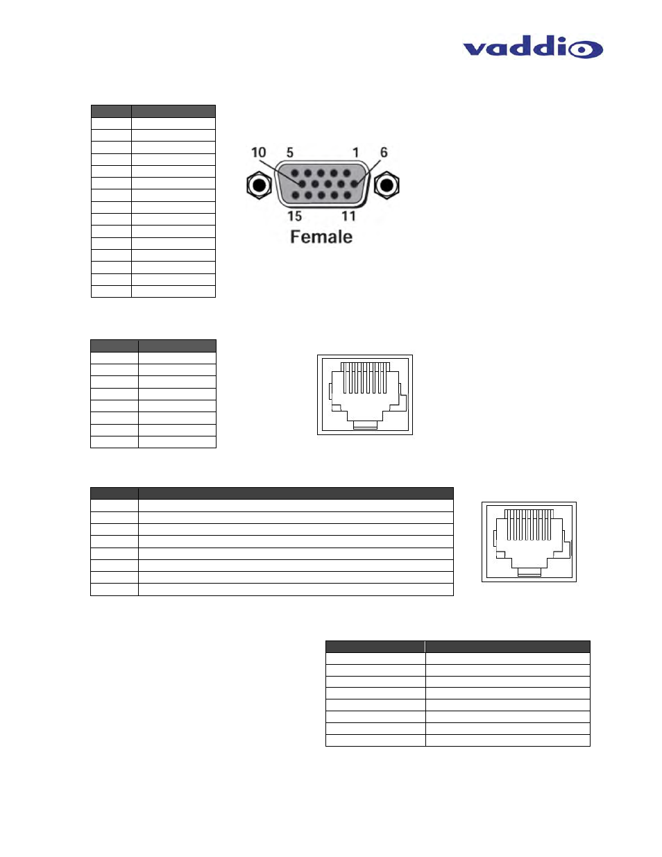
Appendix 1: HD-18 Connector Information
DE-15-F (HD-15F Connector)
EZCamera
Power & HD Video RJ-45 Connector Pin-outs
(For HD-18 Camera and Quick-Connect SR and
Quick-Connect DVI/HDMI SR Interfaces - 568B Wiring Standard)
RS-232 and IR OUT RJ-45 Connector Pin-outs
(For HD-18 Camera and Quick-Connect SR and Quick-Connect
DVI/HDMI SR Interfaces - 568B Wiring Standard)
Communication Specification AutoPresenter or Serial CPU Interface
Communication Speed: 9600 bps
Start bit: 1
Stop bit: 1
Data bits: 8
Parity: None
No Flow control
Notes:
A total of six (6) presets can be accessed with a control
system via RS-232
Each Command must be followed by a line feed
Presets are set up on the Preset-Tracking Camera tabs under the AutoPresenter Camera Preset Area. No trigger assignments
are needed. Set the Tracking Camera position and store the preset. Recall the preset with the commands above.
The Preset OFF command must be issued to return to active tracking.
R99
Pin
YPbPr
1 Pr
2 Y
3 Pb
4 -
5 -
6 Pr
GND
7 Y
GND
8 Pb
GND
9 -
10 -
11 -
12 -
13 -
14 -
15 -
Pin
YPbPr
1 Power+
2 Power-
3 Y+
4 PB+
5 PB
GND
6 Y
GND
7 PR+
8 PR-
Pin #
RS-232 and IR OUT RJ-45
1 Unused
2 Unused
3 -
4 -
5 -
6 GND
7
RXD (from TXD of control source)
8
TXD (to RXD of control source)
RS-232 Command
Description
P00
Preset Off (back to active tracking)
P01
Preset 1 for Tracking camera
P02
Preset 2 for Tracking camera
P03
Preset 3 for Tracking camera
P04
Preset 4 for Tracking camera
P05
Preset 5 for Tracking camera
P06
Preset 6 for Tracking camera
R99
CPU Reset Command
12345678
12345678