3 self test mode, 4 error recovery – Pulsafeeder Pulsar ECA NEMA7 User Manual
Page 20
14
5.3 Self Test Mode
The ECA has a diagnostic test mode which can be used to verify performance and troubleshoot
problems. To initiate the self-test:
1. Remove power from the ECA, and remove the top cover.
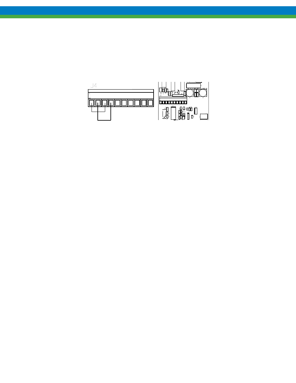
2. Disconnect any field wires attached to J4, and connect Analog Out to Analog In. (jumper J4-1 to
J4-3 and J4-2 to J4-4).
Figure 11
3. Press and hold the WHITE button.
4. Apply power to the ECA. The ECA will enter the self-test mode and perform the following tests:
1. Calibrates mechanical zero position, if necessary.
d) Drives to the 0% stroke position, testing the motor drive and the encoder. Both LED’s
will blink if the zero calibration fails.
e) Pauses for 30 seconds, then confirms that the analog output and the analog input are
correct. Sets trouble code 22 if analog ports do not agree.
f) Drives to the 100% stroke position, testing the motor drive and the encoder. Sets the
trouble code to 13 if the 100% position is not attainable.
g) Pauses for 30 seconds, then confirms that the analog output and the analog input are
correct. Sets trouble code 23 if analog ports do not agree.
h) Confirms that the motor thermistor is reading in correct range. Sets trouble code 24 if
thermistor readings are outside specifications.
i) Sets trouble code 33 to indicate test passed.
5. Turn power off to the ECA, and remove the jumpers installed in step 2. Re-connect field wires.
6. Replace the cover (see Section 4.3) and return power to the ECA.
5.4 Error
Recovery
In cases of abnormal operation, the following procedure is recommended:
1. First, check all power and process connections to ensure all wiring is secure and properly
connected.
2. Check the internal connections within the ECA, ensure that the molded plugs from the stroke
adjustment motor and encoder are secure.
3. Perform a Factory Re-initialization, as described in Section 4.9. This will also force a new
mechanical zero calibration to be performed. The pump motor should be operating during this
process as the ECA will adjust stroke to re-locate the zero position. Ensure that it is safe to
operate the pump during this step.
4. Perform a new analog input signal calibration as per Section 4.7.1.
5. Perform a new analog output signal calibration as per Section 4.7.3.