3 analog output signal calibration – Pulsafeeder Pulsar ECA NEMA7 User Manual
Page 17
11
4.7.3 Analog Output Signal Calibration
T
HIS PROCEDURE REQUIRES REMOVAL OF THE ENCLOSURE COVER
.
T
HIS SHOULD BE
DONE ONLY IF THE AREA IS KNOWN TO BE NON
-
HAZARDOUS
.
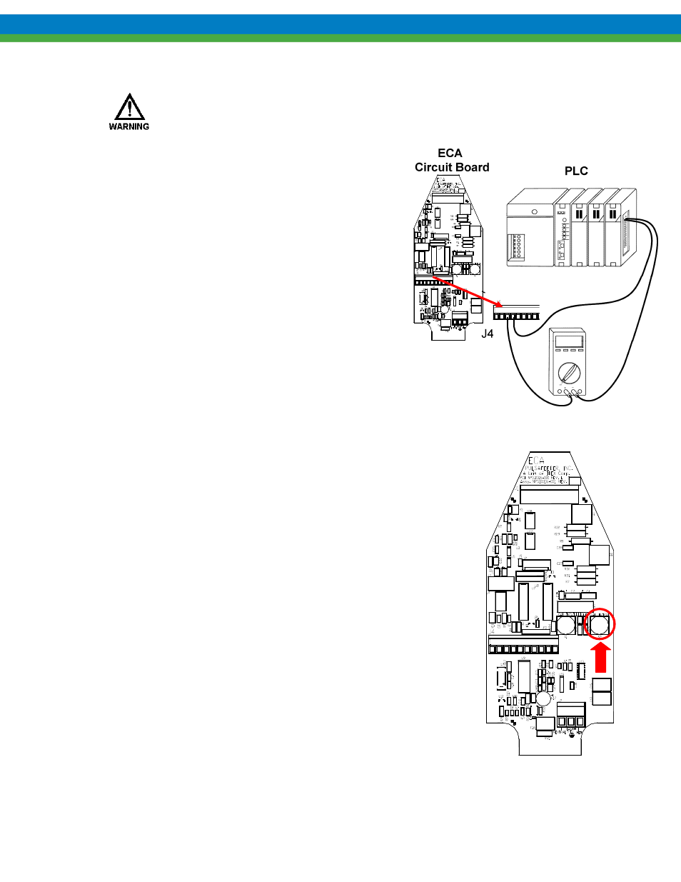
To calibrate the analog output, you need to attach
an ammeter to the output circuit, or have the ECA
wired to the PLC or other device. It is
recommended that you calibrate to the actual
remote equipment and set the analog output values
at whatever is required by that equipment. For
example, the ECA output can be adjusted at the
zero point so that the screen on the PLC system
reads zero %, regardless of the actual mA value of
the signal. The ECA will not actuate to change
stroke length during this process.
Figure 9
1. With the cover removed and power supplied to the ECA, press the
black Output Cal pushbutton. The Cal Output LED will blink
slowly and current output will be set to the present analog out low
calibration value. (4 mA factory default)
2. Press and hold the white Input Cal pushbutton to increase current
output until the desired low setpoint is reached. Release and press
again to decrease current output. Current will change in steps of
approximately 0.02 mA, at a rate of 20 steps per second.
3. Press the black Output Cal pushbutton. The Cal Output LED will
blink rapidly and current output will be set to the present analog
out high calibration value. (20 mA factory default)
4. Press and hold the white Input Cal pushbutton to decrease current
output until desired high setpoint is reached. Release and press
again to increase current output. Current will change in steps of
0.125 mA at a rate of 20 steps per second.
5. Press the black Output Cal pushbutton. The Cal Output LED will
extinguish, unless the minimum span of 2.0 mA is violated, then
the ECA will return to step 1 above.
6. Replace the cover (see Section 4.3) and return power to the ECA.
Figure 10