Pulsafeeder Pulsar ECA NEMA7 User Manual
Page 12
6
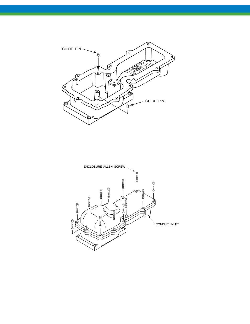
3. Verify that the mating surface of the lower half of the ECA is clean.
4. Verify the guide pins are in place in the lower half of the ECA housing.
Figure 2
5. Position the housing cover over the lower half and set in place. Do not force the cover as
difficulty in assembly indicates mis-alignment.
6. Insert and hand-tighten the 13 Allen screws at first.
Figure 3
7. Check the cover joint using a 0.0015in (0.038mm) feeler gage. Clearance should be less than
0.0015in (0.038mm) such that the feeler gage will not enter the joint more than 0.125in
(3.2mm) at any point. If necessary, torque the cover bolts to a maximum of 100in-lb (11.3N-
m). Use a criss-cross pattern to tighten the bolts to ensure a proper seal around the entire
perimeter.
8. Return the ECA to the desired operating condition.