4 electrical wiring – Pulsafeeder Pulsar ECA NEMA7 User Manual
Page 13
7
4.4 Electrical
Wiring
While the ECA wiring requirements are very simple, always keep in mind that access to these
connectors requires the removal of the cover, and as such this procedure should only be performed
if the area is known to be non-hazardous.
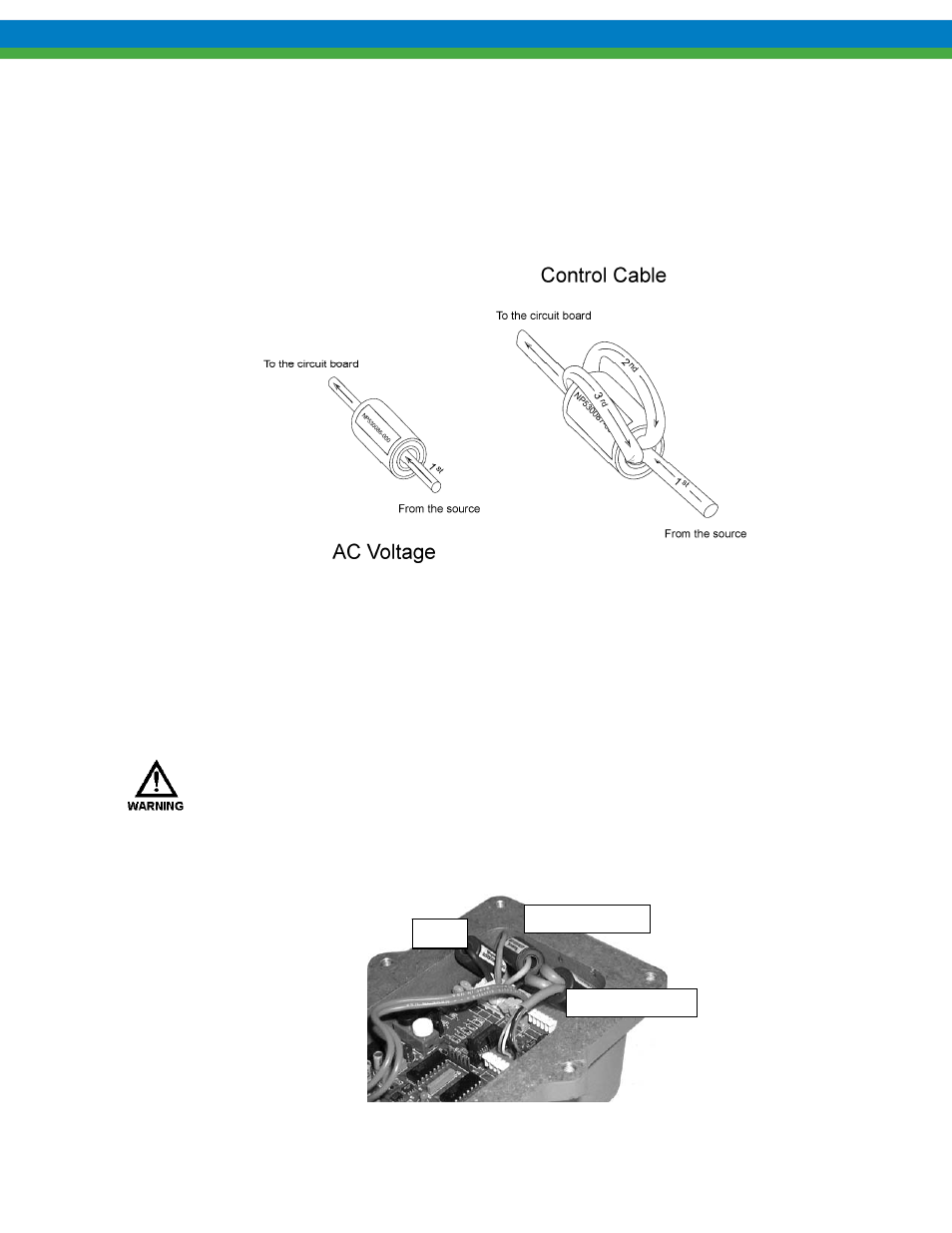
As part of the electrical wiring, a Ferrite core must be used in-line with your connections to meet
EMC emission and immunity standards.
Figure 4
Connections to be made:
1. AC voltage supply. (Each leg is fed separately through part # NP530086-000 once [Line &
Neutral].)
2. Control Cable(s) input (e.g., 4-20mA in, 4-20mA out, and Motor On/Off). (Wire(s) must be
fed through part # NP530087-000 three times.)
F
AILURE TO USE THE PROVIDED
F
ERRITE
C
ORES CAN CAUSE EXCESSIVE
EMC
EMISSIONS
TO BE GENERATED BY THIS DEVICE OR REDUCE ITS IMMUNITY TO EXTERNAL EMISSIONS
,
WHICH COULD LEAD TO ERRATIC AND POSSIBLY UNSAFE OPERATING CONDITIONS
.
Use caution when replacing the cover. If placed improperly, the Ferrite Cores could damage the
motherboard. The example below shows proper core location.
Figure 5
Line
Control Cable(s)
Neutral/ Line 2