6 control input and output connections, 1 motor status input, 2 analog current input – Pulsafeeder Pulsar ECA NEMA7 User Manual
Page 15: 3 analog current output
9
4.6 Control Input and Output Connections
4.6.1 Motor Status Input
The contactor or motor starter controlling the PULSAR motor should be equipped with a normally
open auxiliary contact, which closes to indicate the PULSAR motor is on. This auxiliary contact,
which must be an un-powered, dry contact only, is to be wired to inputs (J4-5 and J4-6) at the
ECA, after removing the factory installed jumper wire. It is critical that the ECA receive this
input, as stroke length should only be adjusted when the pump motor is running. An alternate
contact that represents motor status (for example a relay contact in a local control cabinet) can also
be used for this function.
D
AMAGE TO THE
ECA
MAY OCCUR IF THE STATUS INPUT WIRING RECOMMENDATIONS
ARE NOT FOLLOWED
.
4.6.2 Analog Current Input
The Analog Input is used for remote control of the pump flow. It accepts current inputs anywhere
in the range of 0 to 25mA (e.g., 4-20mA) provided the “span” (the difference between the high
and low value), is greater than 2mA. Use size AWG 16 to AWG 28 wire for hookup. Attach the
positive lead to J4-1 and the negative lead to J4-2. Position indicators are printed on the circuit
board below the terminal. The ECA will provide approximately 160 ohms of resistance to a
current loop. The Analog Input is isolated from all other inputs, outputs and earth ground.
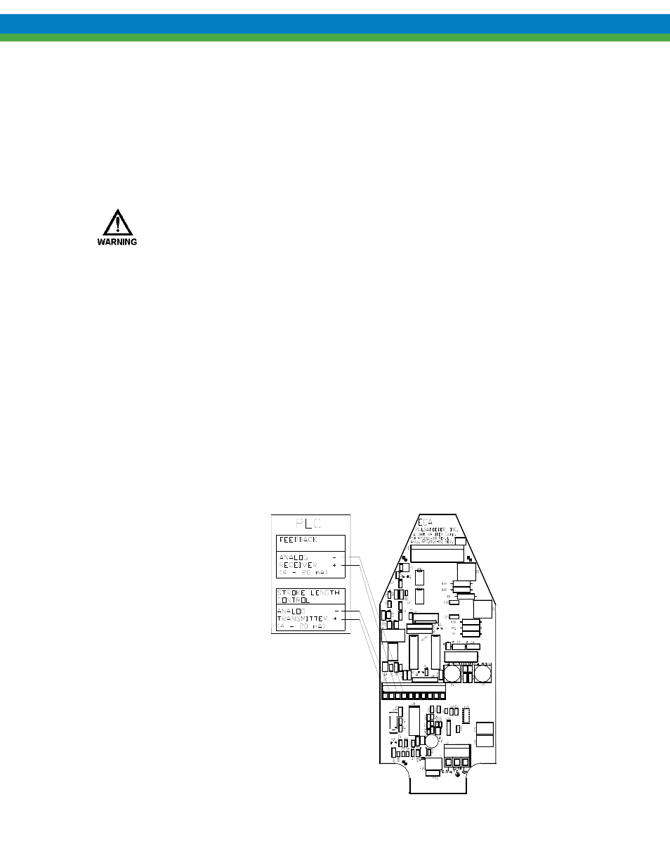
4.6.3 Analog Current Output
The Analog Current Output Channel follows the stroke length position. It can be calibrated to
source current in the 0 to 25 mA range (4-20mA factory default). The output can be calibrated for
reverse acting or split ranging operation. The Current Output can be used to control slave devices
(e.g., ECA 's, ELMA's, PULSAMATICs, etc.) or to fulfill closed loop system requirements. Use
size AWG 16 to AWG 28 wire for hookup. Attach the positive lead to J4-3 and the negative lead
to J4-4. The analog output will drive a maximum load of approximately 700 ohms. The Analog
Output is isolated from all other inputs, outputs, and earth ground.
ref. Section 4.6.3,
Analog Output
ref. Section 4.6.2,
Analog Input