Ke2 evaporator efficiency, Figure 4 - coil sensor placement, Additional inputs – Nor-Lake Enviro-Control IOM User Manual
Page 5
KE2 EvaporatorEfficiency
Installation Instructions
holder. Depress slightly and turn 1/4 turn counterclockwise to
remove. Replace by depressing slightly and turning 1/4 turn
clockwise. Do not overtighten.
The board uses a pluggable screw terminal connector to con-
nect incoming power. The terminal is located in the top right
corner of the controller when the terminals are facing the user.
See Figure 5.
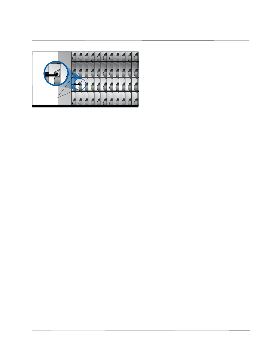
Coil
Sensor
Defrost
Heaters
Figure 4 - Coil Sensor Placement
Fan and Defrost Relays - There are 2 larger relays on the con-
troller with spade connectors. These are used for the evaporator
fans and defrost heaters. Due to the spacing of the enclosure
the spades require a 90 degree terminal. KE2 Therm has includ-
ed (4) spade connectors to assist in wiring the relays.
Evaporator Fan Relay - The fan relay is rated 10A inductive at
240V. One leg of the incoming power for the fans should be
connected to the COM terminal of the fan relay, the upper of the
two larger relays. The remaining leg, (L2) should be connected
to one lead of the fan. The remaining fan lead should be con-
nected to the NO (Normally Open) terminal on the fan relay. See
Figure 7.
Defrost Heater Relay - The heater relay is rated 20A resistive at
240V. One leg of the incoming power for the heaters should be
connected to the COM terminal of the heater relay, the lower
of the two larger relays. The remaining leg, (L2) should be con-
nected to one lead of the heater. The remaining heater lead
should be connected to the NO (Normally Open) terminal on
the heater relay.
Compressor/Liquid Line Solenoid Relay - The compressor re-
lay is rated at 3A induction at 240V. This relay uses the 3-position
pluggable screw terminal to make the connection to the board.
The relay is not intended to control the compressor directly. It is
designed to be used to control the liquid line solenoid or as a pi-
lot to the compressor contactor. One leg of the incoming power
supply (L1) should be connected to COM terminal of the com-
pressor relay, the upper of the two smaller relays. The remaining
leg, (L2), should be connected to one lead on the solenoid/com-
pressor contactor. The remaining lead, should be connected to
the normally open (NO) position on the terminal.
Alarm Relay - The alarm relay is rated at 3A inductive at 240V.
This relay uses the 3-position pluggable screw terminal to make
the connection to the board. The relay may be used to connect
an audible alarm, light, or to alert a 3rd party alarm system. One
leg of the incoming power supply (L1) should be connected to
COM terminal of the alarm relay, the lower of the two smaller
relays. The remaining leg, (L2), should be connected to one lead
on the alarm. The remaining alarm lead, should be connected to
the normally open (NO) position on the terminal.
After all high voltage wiring is completed the metal shield
must be replaced and screws tightened .
Additional Inputs
Suction Temperature Sensor - The suction temperature sen-
sor is required when applying the controller with an electronic
expansion valve. The sensor’s proximity to the evaporator out-
let differs slightly for electronically controlled valves from the
placement of a TEV bulb. Due to the more refined control from
an electronically controlled valve, the sensor must be placed
as close to the outlet of the coil as feasible. Although the dis-
tance from the outlet is different, the nature of the refrigerant’s
flow through the tube remains unchanged, thus the orientation
of the sensor remains at the 4 or 8 o’clock position. The sensor
should be secured to the suction line using the included wire
ties designed for low ambient operation.
Pressure Transducer - In addition to the suction temperature
sensor, a pressure transducer is also required for superheat
measurement when applying an electronic expansion valve.
The pressure tap should be mounted on the top of a horizontal
section of tube. It should be located near the suction sensor, ap-
proximately 3 inches downstream from the position of the tem-
perature sensor.
Auxiliary Temperature Sensor -The auxiliary temperature sen-
sor provides flexibility and may be used for any purpose desired
by the user. The placement of the sensor is dependent on the
requirements of the user’s intended application. The Auxiliary
Temperature sensor must be supplied by KE2 Therm.
Digital Inputs - The controller includes (3) digital inputs. See
Table 3 for configuration options.
5
01/13 Rev. A 151627
Enviro-Control™