Electric defrost - surface heater, Electric defrost - dropped tube, Air defrost – Nor-Lake Enviro-Control IOM User Manual
Page 4: Ke2 evaporator efficiency, Figure 3 - proper sensor location
KE2 EvaporatorEfficiency
Installation Instructions
After the sensor is installed, route the wire back to the control-
ler location. When routing sensor wire, it is important to avoid
interference from high voltage lines. If sensor wire is run parallel
to the high voltage, there is a potential for inductance to affect
the sensor reading. This is of particular concern with long wire
runs. When extending sensors, use the 18 gage, shielded twist-
ed pair. Sensor wires can be run beyond 100 feet when using
special considerations. Contact KE2 Therm. After the wire has
been successfully routed, it may be connected to the pluggable
terminal on the controller.
Coil Temperature Sensor - As a critical input to the control-
ler, it is essential the sensor is located at the coldest point on
the evaporator coil for optimal operation. The coil sensor is an
integral part of the control algorithm used to determine coil ef-
ficiency, to initialize defrosts, and to terminate defrosts.
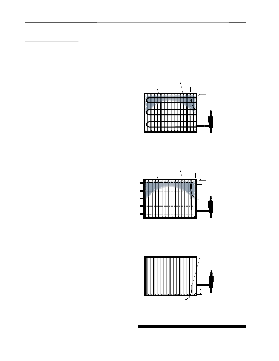
KE2 Therm offers general guidance for sensor locations based
on the coil construction. Figure 3 shows the recommended lo-
cations for the coil sensor for each evaporator type.
When installing on draw through models, the sensor should be
located behind the coil in the lower corner nearest the suction
header. Blow through models should be installed on the front of
the coil, in the upper corner also nearest to the suction header.
When installing the sensor into the coil, the sensor should be po-
sitioned half way between the circuit tubes and, perpendicular
to the face of the coil. When choosing the location, the sensor
should not be located adjacent to the electric heating elements.
Locating the sensor too close to the elements will cause false
defrost termination temperatures. The sensor should be ap-
proximately half the distance between the heaters if possible.
Figure 4 shows the proper sensor placement.
Due to the many factors influencing the evaporator perfor-
mance, it is impossible for KE2 Therm to provide the proper loca-
tion of every installation. However, the coil sensor is an integral
part of the control algorithm used to determine coil efficiency
to initiate, as well as, terminate defrosts. The coldest point in
the coil can be identified from existing system knowledge or by
monitoring the normal operation.
Controller Power - The high voltage wiring is protected by
a metal shield screwed to the back side of the controller. The
shield should be removed to gain access to the wiring connec-
tions, making note of the location of the screws. The screws in
the upper corners are coarse thread screws, while the screw in
the middle is a 4-40 machine screw.
The controller accepts either 115V or 208/240V incoming power.
The controller includes metal oxide varistors (MOVs), providing
protection from voltage spikes. MOVs use the same technology
commonly applied to protect consumer electronics. They func-
tion by filtering out voltages high enough to damage the board.
When the voltage exceeds the allowed amount, the MOVs short
to ground, protecting the circuitry. For additional protection,
the board has a replaceable BK/MDL-1/4 fuse in line. The grey
plug is accessible without removing the metal shield in the fuse
1/2 way
- 1/2 way between heater coils
- insert perpendicular to face of coil
- pinch fins together to hold
Heater Coil
Ideal Sensor Location
Higher Frost Zone
coldest part of
evaporator
Electric Defrost - Surface Heater
- 1/2 way between heater coils
- approx. 3” from top and 3”
from side
- insert parallel to face of coil
- pinch fins together to hold
Heater Coil
Ideal Sensor Location
Higher Frost Zone
coldest part of
evaporator
Electric Defrost - Dropped Tube
- lower corner nearest expansion
valve, approx. 3” from bottom,
and 3” from side
- insert parallel to face of coil
- pinch fins together to hold
Ideal Sensor Location
Air Defrost
3”
3”
3”
3”
3”
Figure 3 - Proper Sensor Location
4
01/13 Rev. A 151627
Enviro-Control™