Air sensor >6, Ke2 evaporator, Installation & wiring – Nor-Lake Enviro-Control IOM User Manual
Page 3: Location, Return air figure 2 - return air sensor placement
KE2 Evaporator
Installation Instructions
.
s
u
t
a
t
s
m
e
t
s
y
s
r
o
/
d
n
a
e
r
u
t
a
r
e
p
m
e
t
m
o
o
r
e
h
t
f
o
g
n
i
w
e
i
v
y
s
a
e
r
o
f
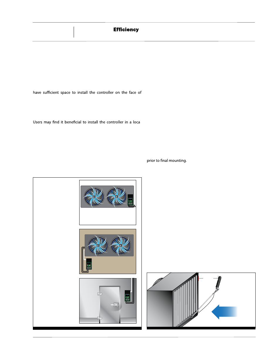
See Figure 1 for locations.
If installing the controller on the face of the evaporator, preexist-
ing knockouts on the evaporator should be used for installing
the high voltage wiring. If knockouts do not preexist, hole(s)
may be carefully cut into an unobstructed area of the evapora-
tor case. If modifying the face of the evaporator is not feasible
or desired, the controller’s conduit knockouts may be used with
½ inch conduit.
The bottom side of the controller includes a cutout with cable
tie slots providing a strain relief for the low voltage and sensor
wires. Additional knockouts are available on either side if con-
duit is preferred.
Installation & Wiring
The KE2 Evap is supplied with pluggable connectors for all
connections. Pluggable connectors permit the controller to
be placed in a safe location while the wiring is installed. They
also simplify the wiring, allowing the wires to be fastened to the
screw terminals in the open air. Once all wiring is completed
using accepted wiring practices, it is plugged into the controller
Although there is one pressure transducer and four temperature
sensor inputs, when used with mechanical valves (TEVs), KE2
Evap only requires the (2) sensors supplied with the kit. One
sensor reads the return air temperature and the other measures
the coil temperature. NOTE! Sensor location is critical to the
proper operation of the controller.
Return Air Temperature Sensor - The air temperature sensor is
installed in the return air of the evaporator using the included
sensor mount. Most applications allow the sensor mount to
be installed using an existing screw. On evaporators where us-
ing an existing screw is not possible, the included self-tapping
screw may be used to secure the sensor mount to the evapora-
tor. Note: Be careful to avoid damage to an evaporator tube
or causing a leak in the drip pan. When installing, it is impor-
tant to prevent the air sensor from coming into contact with the
mounting bracket, cable ties, or any other solid material. Figure
2 shows an example of how to mount the sensor. The sensor
must be a minimum of 6 inches from the coil surface.
Location
The KE2 Evap was developed with ease of installation in mind.
The controller is supplied in an enclosure, and encapsulated to
protect the circuitry from moisture damage. This extra level of
protection allows the controller to be installed in the refriger-
ated space.
When installing the controller, it may either be installed on an
interior/exterior wall or on the evaporator. Many evaporators
evaporator or on its housing. Locating the controller as close to
the evaporator as possible reduces the amount of wiring when
converting existing systems, as well as when it is applied on new
applications.
-
tion providing easy access -- on the wall or near the entrance.
This enables the user to easily view the display, and eliminates
the need to use a ladder or lift to modify the setpoints or check
alarms.
If viewing the temperature outside the walk-in or refrigerated
room is desirable, the KE2 Evap may be used as a digital thermo-
stat. The controller is then installed near the door of the space
KE2 EvaporatorEfficiency
TM
thermsolutions
ENTER
BACK
2
2
KE2 EvaporatorEfficiency
TM
thermsolutions
ENTER
BACK
2
2
KE2 EvaporatorEfficiency
TM
thermsolutions
ENTER
BACK
2
2
On the wall
On the evaporator
At the entrance
Figure 1 - KE2 Evap Installation Locations
Air
Sensor
>6”
Return Air
Figure 2 - Return Air Sensor Placement
3
01/13 Rev. A 151627
Enviro-Control™