Ke2 evaporator efficiency, Table 3 - controller menus and menu parameters, Parameter name description – Nor-Lake Enviro-Control IOM User Manual
Page 13: Parameter name description range default, Dig in setting status displayed on controller, Installation instructions, Variables menu, Alarms status menu, Manual menu, Variables menu options for dig in mode
KE2 EvaporatorEfficiency
Installation Instructions
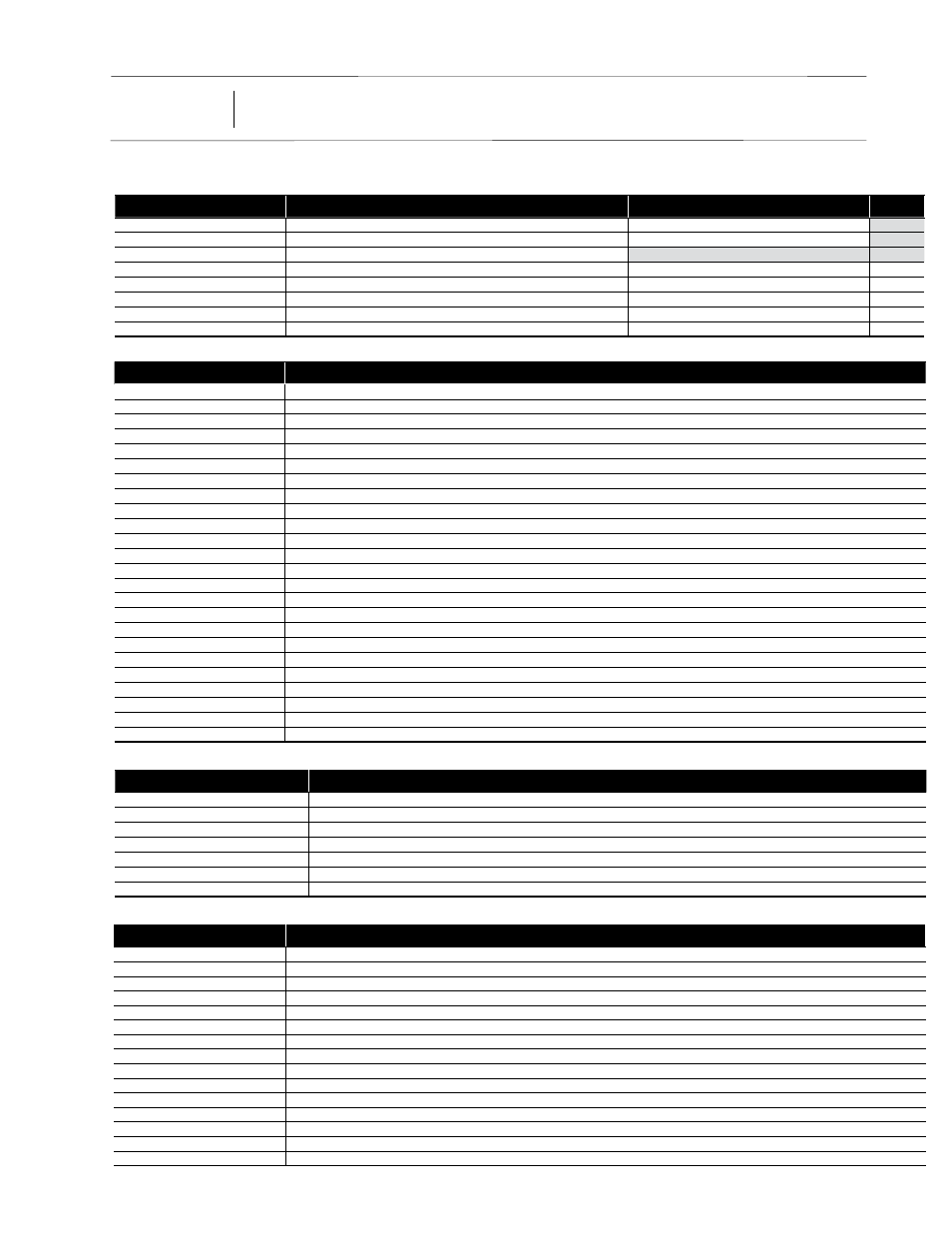
Table 3 - Controller Menus and Menu Parameters
Parameter Name
Description
NO ALARM
No alarms active, everthing is running correctly
PRESSURE SENSOR
Suction pressure sensor is shorted, open or pressure out of range
SUCTION TEMP SENSOR
Suction temperature sensor is shorted or open
AIR TEMP SENSOR
Return air temperature sensor is shorted or open
COIL TEMP SENSOR
Coil temperature sensor is shorted or open
AUX TEMP SENSOR
Auxiliary temperature sensor is shorted or open
HIGH SUPERHEAT
Superheat above upper limit
LOW SUPERHEAT
Superheat below lower limit
HIGH AIR TEMP
Room temperature is above ROOM TEMP + AIR TEMP DIFF + HIGH TEMP ALARM OFFSET for longer than HIGH TEMP ALARM DELAY
LOW AIR TEMP
Room temperature is below ROOM TEMP - LOW TEMP ALARM OFFSET for longer than LOW TEMP ALARM DELAY
EXCESS DEFROST
Three consecutive defrosts with less than a one hour interval between each defrost
DEFR TERM ON TIME
Defrost terminated on time instead of temperature for two consecutive cycles
DOOR SWITCH
If door is open and room temperature is 5 degrees above ROOM TEMP + AIR TEMP DIFF for DOOR ALARM DELAY time
COMMUNICATION ERROR
ONLY FOR BONDED CONTROLLERS: No communication between controllers for one minute or more
EXT ALARM
If DIG IN (1, 2 and/or 3) MODE = EXT ALARM: The digital input is in an active state
Parameter Name
Description
Range
Default
MANUAL CONTROL
Force the controller into the next operating mode
REFRIGERATE, OFF, DEFROST, DRIP TIME, FAN DELAY
MANUAL VALVE
Manually open or close the EEV in percentage increments
1% increment
CLEAR ALARMS
Clear all active alarms
MANUAL COMPRESSOR RELAY
Manually energize or de-energize liquid line solenoid /compressor relay
AUTO (ON/OFF), MANUAL OFF, MANUAL ON
AUTO
MANUAL DEFROST RELAY
Manually energize or de-energize defrost relay
AUTO (ON/OFF), MANUAL OFF, MANUAL ON
AUTO
MANUAL FAN RELAY
Manually energize or de-energize evaporator fan relay
AUTO (ON/OFF), MANUAL OFF, MANUAL ON
AUTO
DHCP
ADVANCED TOPIC, SEE USER GUIDE: Selects appropriate DHCP mode
OFF, CLIENT, SERVER
OFF
FACTORY RESET
Reset the controller to the factory default setpoints
RESET
Parameter Name
Description
ROOM TEMP
Room temperature as measured by the controller
COIL TEMP
Coil temperature as measured by the controller
SYSTEM MODE
Current operating status
SUPERHEAT
Superheat as calculated by the controller (requires suction pressure transducer and suction temperature sensor)
SUCTION PRESSURE
Suction pressure as measured by the controller
SUCTION TEMP
Suction temperature as measured by the controller
SATURATION TEMP
Saturation temperature as calculated by the controller
VALVE % OPEN
Percentage the EEV is open
AUX TEMP
Auxiliary Temperature (Taux) sensor reading as measured by the controller
COMPRESSOR RELAY
Current state of liquid line solenoid/compressor relay
DEFROST RELAY
Current state of the defrost relay
FAN RELAY
Current state of the evaporator fan relay
DIG 1 STATUS
Current status of the Digital Input #1
DIG 2 STATUS
Current status of the Digital Input #2
DIG 3 STATUS
Current status of the Digital Input #3
IP OCTET 1
The first three digits of the IP address
IP OCTET 2
The second three digits of the IP address
IP OCTET 3
The third three digits of the IP address
IP OCTET 4
The fourth three digits of the IP address
SUBNET MASK OCTET 1
The first three digits of the subnet mask address
SUBNET MASK OCTET 2
The second three digits of the subnet mask address
SUBNET MASK OCTET 3
The third three digits of the subnet mask address
SUBNET MASK OCTET 4
The fourth three digits of the subnet mask address
FIRMWARE VERSION
Current version of the firmware on the controller
Variables Menu -
Non Adjustable (view only)
Alarms Status Menu
Non Adjustable (view only)
Manual Menu
DIG IN Setting
Status Displayed on Controller
DIG IN MODE = DISABLED
DISABLED
DIG IN MODE = 2ND (ROOM) TEMP
inactive = 2ND ROOM TEMP OFF; active = 2ND ROOM TEMP ON
DIG IN MODE = DOOR SWITCH
inactive = DOOR CLOSED; active = DOOR OPEN
DIG IN MODE = EXT ALARM
inactive = NO ALARM; active = EXT ALARM (x)
DIG IN MODE = SYSTEM OFF
inactive = SYSTEM ON; active = SYSTEM OFF
DIG IN MODE = LIGHT SWITCH
inactive = LIGHTS OFF; active = LIGHTS ON
DIG IN MODE = CAMERA SWITCH
inactive = CAMERA OFF; active = CAMERA ON
Variables Menu Options for DIG IN MODE
13
01/13 Rev. A 151627
Enviro-Control™