Lyntec, Rpcm, Table 1-1: front panel display components – Lyntec RPCM User Manual
Page 6
139-0498-01.6
6
Chapter One--Overview
Front Panel Overview
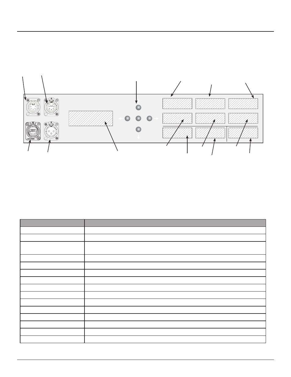
Figure 1–1 shows the parts of the RPCM front
panel. A brief description of each part follows in
Table 1–1.
Figure 1-1: RPCM Front Panel Display
A
B
C
D
E
F
G
H
I
J
K
L
M
N
O
Table 1-1: Front Panel Display Components
Component
Description
A. DMX in
DMX 512 Input, isolated
B. DMX Out
DMX 512 Output, buff ered, isolated.
C. Network Port
Connects the cabinet to a computer or network for initial setup or operation using the
built-in web interface (RJ-45) and/or sACN.
D. Override
Dry contacts for EO and EL functions--See Chapter 4
E. LCD Screen
Screen shows RPCM information.
F. Navigation Buttons
Navigates the LCD screen menus
G. VAC L-N Phase A
Displays voltage for phase A
H. VAC L-N Phase B
Displays voltage for phase B
I. VAC L-N Phase C
Displays voltage for phase C
J. Current Phase A
Displays current in amperes for phase A
K. Current Phase B
Displays current in amperes for phase B
L. Current Phase C
Displays current in amperes for phase C
M. VAC Neutral to Ground
Displays neutral to ground voltage
N. Neutral Current
Displays current in amperes for the neutral
O. Frequency
Displays AC frequency in Hz
Front Panel Overview
LynTec
RPCM
DMX
IN
OUT
Network
Override
A
B
C
VAC L-N
VAC L-N
VAC L-N
AMPS
AMPS
AMPS
VAC N-G
AMPS
Hz
NEUTRAL
PHASE
OK