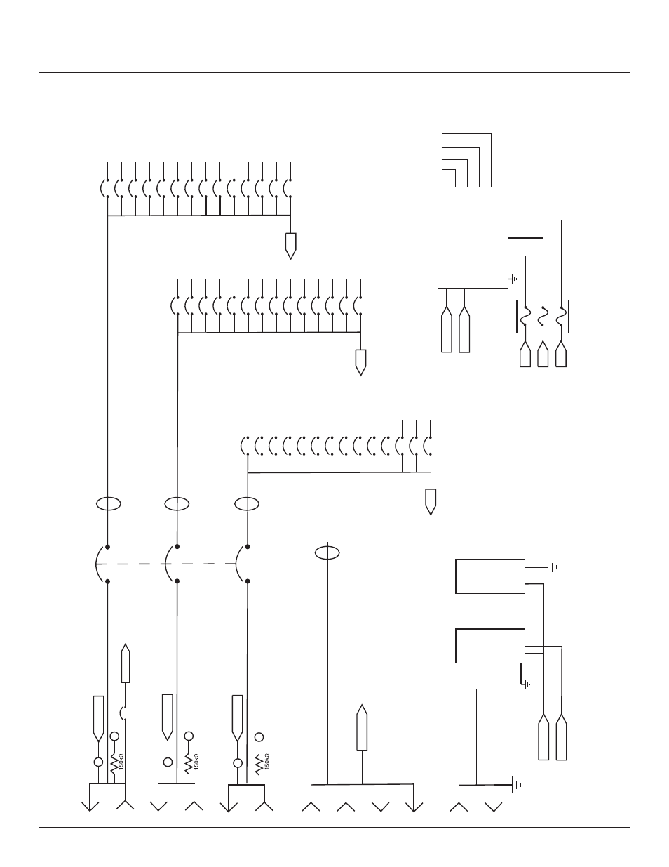
Appendix d--rpc system diagrams and schematics, Rpcm schematic – Lyntec RPCM User Manual
Page 36
139-0498-01.36
Appendix D
36
Appendix D--RPC System
Diagrams and Schematics
NEUTRAL
C
C
B
B
A
A
L
R
16
4
40
3
9
10
15
21
22
27
28
33
34
39
18
6
42
5
11
12
17
23
24
29
30
35
36
41
14
2
38
1
7
8
13
19
20
25
26
31
32
37
CONTROL
IN
OUT
IN
OUT
IN
OUT
IN
OUT
IN
OUT
400A
400A
400A
400A
400A
Phase A (Black)
Phase B (Red)
Phase C (Blue)
Neutral (White)
Ground (Green)
#12AWG THHN (x42--one per circuit)
#12AWG THHN
(x42--one per circuit)
2/0 AWG
2/0 AWG
2/0 AWG
TP-A
TP-B
TP-C
PL-C
PL-B
PL-A
CT-1
CT-2
CT-3
CT-4
24V
Power
Supply
Voltage
Trans-
s-
Ducer
CT Input
Branch Circuit
CT strips
F-1
F-3
BCPM-A
Voltage Monitor Input
ECB14020G3 Circuit Breaker
120V-20A 80%
CONTROL
NEUTRAL
NEUTRAL
NEUTRAL
CONTROL
NEUTRAL
RPCM Schematic
NEUTRAL
Circuit Breaker QOU120
4
1 2 3