COOK ETS User Manual
Page 2
2
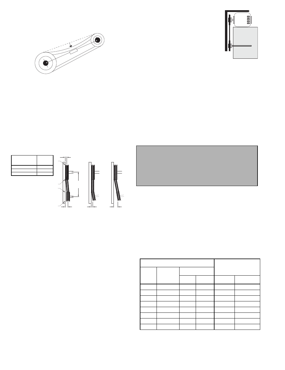
Pulley Alignment
Pulley alignment is adjusted by loosen-
ing the motor pulley setscrew and by mov-
ing the motor pulley on the motor shaft.
Figure 2 indicates where to measure the
allowable gap for the drive alignment toler-
ance. All contact points (indicated by
WXYZ) are to have a gap less than the tol-
erance shown in the table. When the pul-
leys are not the same width, the allowable
gap must be adjusted by half of the difference in width (As
shown in A & B of Figure 2). Figure 3 illustrates using a car-
penter’s square to adjust the position of the motor pulley until
the belt is parallel to the longer leg of the square.
Wiring Installation
All wiring should be in accordance with local ordinances
and the National Electrical Code, NFPA 70. Ensure the
power supply (voltage, frequency, and current carrying
capacity of wires) is in accordance with the motor name-
plate. Refer to the Wiring Diagrams on page 3.
Lock off all power sources before unit is wired to power
source.
Leave enough slack in the wiring to allow for motor move-
ment when adjusting belt tension.
Follow the wiring diagram in the disconnect switch
and the wiring diagram provided with the motor. Cor-
rectly label the circuit on the main power box and
always identify a closed switch to promote safety (i.e.,
red tape over a closed switch).
Fan Installation
The fan support (roof curb) should provide a level surface
for installation. If the roof is pitched more than 1/2:12, a
sloped curb must be used to correct for the incline.
Place fan over roof opening. Secure the fan with lag
screws, anchor bolts, or other suitable fasteners.
Personal Safety
Disconnect switches are recommended. Place the
disconnect switch near the fan in order that the
power can be swiftly cut off in case of an emer-
gency, and in order that maintenance personnel are
provided complete control of the power source.
Recommended Torque for Setscrews/Bolts (IN/LB.)
Setscrews
Hold Down Bolts
Size
Key Hex
Across
Flats
Recommended
Torque
Min.
Max.
Size
Wrench
Torque
No.10
3/32”
28
33
3/8”-16
240
1/4”
1/8”
66
80
1/2”-13
600
5/16”
5/32”
126
156
5/8”-11
1200
3/8”
3/16”
228
275
3/4”-10
2100
7/16”
7/32”
348
384
7/8”-9
2040
1/2”
1/4”
504
600
1”-8
3000
5/8”
5/16”
1104
1200
1-1/8”-7
4200
3/4”
3/8”
1440
1800
1-1/4”-7
6000
Damper Installation continued
d. Operate the dampers manually to ensure the blades
move freely. Dampers should be released from full
open position to check for proper closing.
Motor Installation (Belt Drive fans)
To prevent damage to the fan during shipping, motors 5
HP and larger, and extremely heavy motors (cast iron or
severe duty) are shipped loose and must be field mounted.
a. Remove the motor plate mounting bolts and the motor
plate.
b. Remove the motor mounting bolts from the motor
plate.
c. Mount the motor to the motor plate aligning to the
appropriate holes.
d. Place the motor plate on the power assembly and rein-
stall the mounting bolts.
Belt and Pulley Installation
If your fan is a direct drive, proceed to Wiring Installation.
Belt tension is determined by the sound of the belts when
the fan is first started. The belts will produce a loud squeal,
which dissipates after the fan is operating at full capacity. If
belt tension is too tight or too loose, lost efficiency and
damage can occur.
Do not change the pulley pitch diameter to change ten-
sion. The change will result in a different fan speed.
a. Loosen the motor plate adjustment nuts on motor base
and move motor plate in order that the belts can easily
slip into the grooves on the pulleys. Never pry, roll, or
force the belts over the rim of the pulley.
b. Adjust the motor plate until proper tension is reached.
For proper tension, a deflection of approximately 1/4”
per foot of center distance should be obtained by firmly
pressing the belt. Refer to Figure 1.
c. Lock the motor plate adjustment nuts in place.
d. Ensure pulleys are properly aligned. Refer to Figure 2.
1 foot
1/4 inch
Figure 1
Figure 2
Tolerance
Center Distance
Maximum
Gap
Up thru 12”
1/16”
12” up through 48
1/8”
Over 48”
1/4”
OFFSET
ANGULAR
OFFSET/ANGULAR
A
W
X
Y
Z
B
CENTER
DISTANCE
(CD)
GAP
GAP
Figure 3